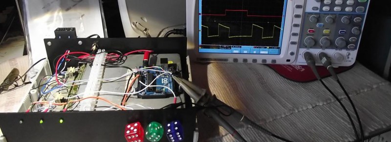
If you are working with OBD2 hardware or software, it’s easy enough to access test data, simply plug into a motor vehicle with an OBD2 socket. If, however, you wish to test OBD2 software under all possible fault conditions likely to be experienced by an engine, you are faced with a problem in that it becomes difficult to simulate all faults on a running engine without breaking it. This led [Fixkick] to create an OBD2 simulator using a secondhand Ford ECU supplied with fake sensor data from an Arduino to persuade it that a real engine was connected.
The write-up is quite a dense block of text to wade through, but if you are new to the world of ECU hacking it offers up some interesting nuggets of information. In it there is described how the crankshaft and camshaft sensors were simulated, as well as the mass airflow sensor, throttle position, and speedometer sensors. Some ECU inputs require a zero-crossing signal, something achieved with the use of small isolating transformers. The result is a boxed up unit containing ECU and Arduino, with potentiometers on its front panel to vary the respective sensor inputs.
We’ve brought you quite a few OBD2 projects over the years, for example, there was this LED tachometer, and a way into GM’s OnStar.
Thanks [darkspr1te] for the tip.


If memory serves scantool.net has ECU simulators.
… For a price
Does it also simulate real world voltage variations on both the sensor and OBD2 sides as well? Can you introduce simulated electrical noise?
easily… set a cellphone on the wires and call it.
I think DIY ECUs will be way more interesting when they don’t actually have to deal with rudimentary stuff like engine timing and shifting. That stuff is nice and all but electric cars are far easier to control.
No fun allowed
thats pretty silly to write. even electric cars have to deal with timing and shifting, just in different ways. FWIW DIY ecus are already pretty cool, for example Megasquirt comes in many flavors and some versions require you to solder it together yourself.
But clearly you didnt read the article, the article is more about exploring the OBD2 communication protocol and testing existing ECU’s. Of which the latter is very hard to do unless you have a running car to test it on and even then it would be impossible to test OBD2 for fault issues if you were not able to create those issues through something such as the test rig shown in the article.
Dice as adjustment knobs.
Well that’s different!
My megasquirt was tested on the bench with this https://www.diyautotune.com/product/megasquirt-stimulator-v2-2-unassembled-kit/ not obd2 but did the job. Maybe this project could use a similar approach
it could but it would limit you to the fault issues that one could test in a way. Some of the ODB2 fault codes deal with intermittent stuff which you would need just a bit more logic and customization to create, you would more than likely still have to work an arduino in there somewhere to accommodate for that.
I don’t know if I’m missing something, but if you only want to test OBD tools you just need to generate the OBD data. You can do this with an Arduino, Microchip etc. You don’t need to generate sensor signals just to get an ECU to do it.
If you want to vary say DID data for engine speed you have a of pot connected to your micro and scale the data accordingly. If you want to be really flash a little program controlling your micro over USB.
Can someone change the Vin# using this method?