DEF CON is starting right now, and this is the year of #badgelife. For the last few years, independent hardware wizards have been creating and selling their own unofficial badges at DEF CON, but this year it’s off the charts. We’ve already taken a look at Bender Badges, BSD Puffer Fish, and the worst idea for a conference badge ever, and this is only scratching the surface.
This is also a banner year for the Hackaday / Tindie / Supplyframe family at DEF CON. We’re on the lookout for hardware. We’re sponsoring the IoT village, [Jasmine] — the high priestess of Tindie — and I will be spending some time in the Hardware Hacking Village, praising our overlords and saying the phrase, ‘like Etsy, but for electronics’ far too much. We’ll be showing people how to solder, fixing badges, and generally being helpful to the vast unwashed masses.
Obviously, this means we need our own unofficial DEF CON badge. We realized this on July 10th. That gave us barely more than two weeks to come up with an idea for a badge, design one, order all the parts, wait on a PCB order, and finally kit all the badges before lugging them out to DEF CON. Is this even possible? Surprisingly, yes. It’s almost easy, and there are zero excuses for anyone not to develop their own hardware badge for next year’s con.
Inspiration
This project began on July 10th. That gives this project only two weeks from conception to design to kitting badges, to physically lugging them over to the con. This is obviously not going to be a complicated badge, but in the space of simple badges, what can we actually do with two weeks of development and manufacturing time?
The first suggestion from [Jasmine] was a simple ‘I Can Solder Badge’, or something like what Partfusion is selling on Tindie. Since we’ll be hanging out at the Hardware Hacking Village — the largest concentration of soldering irons in Vegas this week — an, ‘I can solder’ badge an awesome idea. It’s the perfect introduction to soldering irons.
However, just a few days before these plans came to fruition, I stumbled across an entirely new idea in wearable PCBs. Lapel pins are now a thing. [jglim] discovered ‘butterfly clutch tie tacks’ are effectively SMD components.
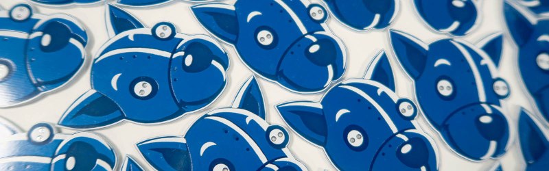
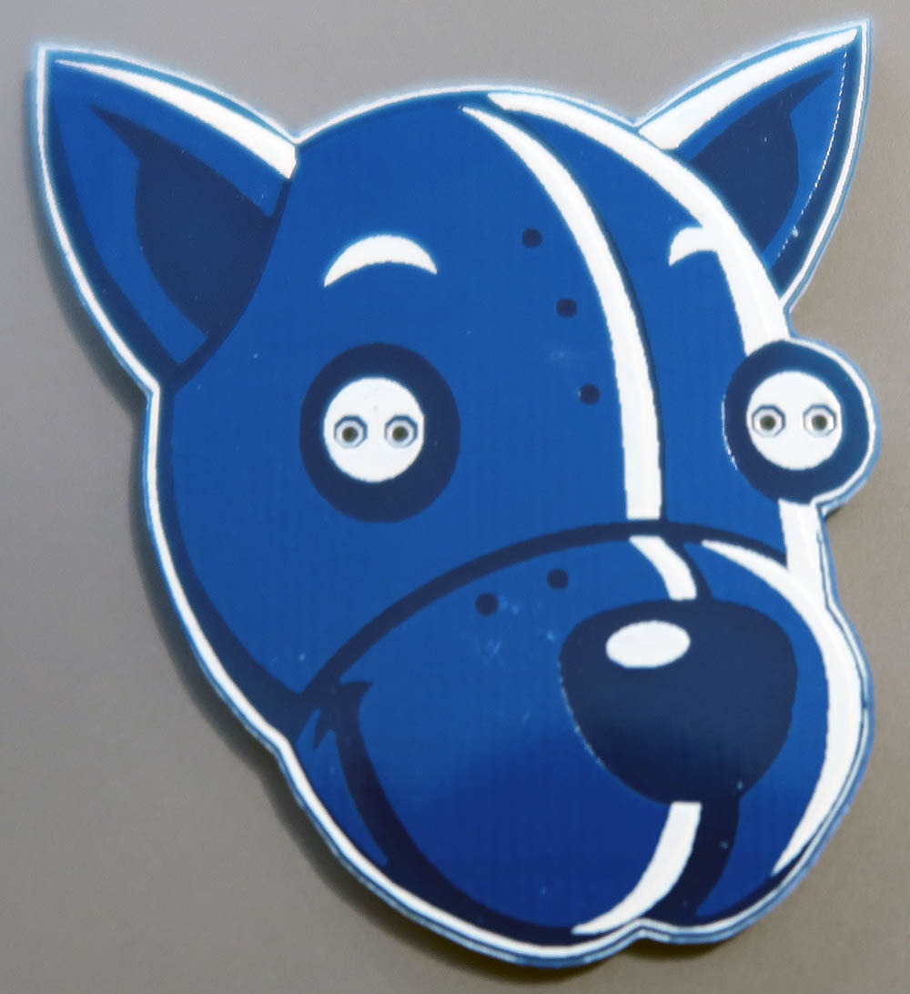
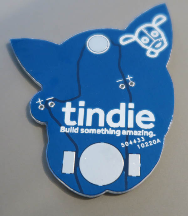
Between those two ideas, [Jasmine] and I eventually came up with a workable idea. We would build a badge in the shape of the head of our lovable robotic mascot, with LEDs for eyes. The circuit would be very simple — just a 3 V, 1220-sized battery and two LEDs — and a pad for the lapel pin clasp on the back. The PCB must fit inside a 50 mm x 50 mm square to get the best pricing from the board house, and the entire top layer, including the copper, would be art.
This is an experimental board, although we’ve seen projects similar to this before. A few months ago, [Andrew Sowa] made money of me using different layers of mask, silk, and copper on the standard OSH Park PCB stackup. [Trammell Hudson] and [Blake Ramsdell] are also doing incredible work with OSH Park PCBs. However, the Tindie mascot is blue, not purple. Anyone can get a PCB with a blue soldermask, but I haven’t seen any experiments exploring the artistic potential of Chinese board house PCBs. There’s only one way to find out if this will work.
Creating the badge
With a somewhat cogent idea of what this badge should be, most of the BOM was already sorted. These ‘badges’ would actually be lapel pins, and we can get hundreds of them from the same AliExpress store [jglim] used. We’ll need bags to contain all these parts, and conveniently this AliExpress store also sells self-adhesive bags to put the board, LEDs, battery, and all the parts in. That’s one order down, and about a fifth of the parts on the BOM.
The battery holder was the most difficult part to source. I don’t really trust AliExpress datasheets, and if I’m building a board around a battery holder, I need to get the dimensions and pads right the first time. The battery holder came from Digikey, and holds a 1216, 1220, or 1225-sized lithium cell.
Amazon Prime is a godsend, and this is what we used to source the LEDs and batteries. Since Tindie’s eyes are different colors, an assorted kit of 5mm LEDs was the best way to go. We also picked up a few multicolor flashing RGB LEDs for extra special glowy blinky stuff.
That only leaves making a PCB. This badge had to be designed and fabricated on a very short timeline, but I like to live dangerously. We went with Seeed’s Fusion PCB service to make the actual PCBs. I’ve had good experiences with them in the past, and since we were paying for DHL shipping to California, we were pretty confident the boards would arrive on time.
The art for this badge was done in Eagle. I know I’m going to get some criticism for the choice of EDA suite, but Eagle is just faster. It only took ten minutes for me to create the ultimate DEF CON badge, and the idea for the Tindie badge is of similar complexity.
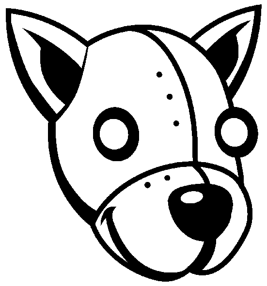
The art for this badge was taken from some work done by our in-house artist [Joe Kim]. The different layers of silkscreen, outline, soldermask, and copper were separated in Illustrator, and each layer converted to a .BMP at 300 dpi. These layers were imported into Eagle one at a time. After that, the only thing left to do was to build a tiny LED circuit on the back of the badge.


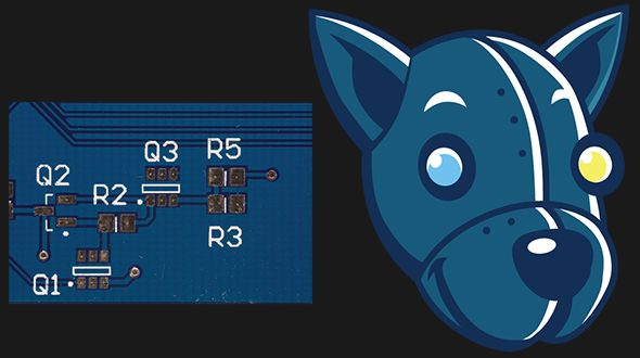
 The circuit for this badge is simple enough: connect the negative terminal of the battery holder to one side of the LEDs, and connect the positive side of the battery terminal to the other side of the LEDs. You should do this with traces, but for such a simple circuit I wanted to experiment. I used copper fills for GND and VCC in the schematic. I would consider this a little more robust, but I will admit my implementation looks like crap.
Apart from that, finishing the back of the board was as simple as adding a Tindie dog head logo and some text on the silk screen.
What was the total cost of creating all of these badges? We ordered enough parts for 300 kits, although we did have to buy 500 battery holders to get the price break. In total, each badge costs about $1.80 USD. Compared to other marketing materials we give away at cons, that’s pretty cheap. We’re calling this a win.
What we’re going to do next time
We managed to create three hundred functional, interesting badges in less than two weeks. That doesn’t mean that there’s not still room for improvement. Using layers of copper, soldermask, and silkscreen for the front of the badge was a successful experiment, but I completely neglected the possibility of using bare, HASL copper in the badge’s color palette. That’s what we’re going to do for the next revision.


I HATE those tracking numbers. For a while, the place I was using had been very consistent about putting the number on the top layer of the board, so I got smart and flipped my design front-to-back before making the gerbers. That time, they decided to put the number on the bottom layer.
I’ve never gotten any board from Elecrow that has them… ;) Just sayin’!
I got deja vu reading this…
It’s almost like the content has been cut and pasted twice. ;)
That is super bizarre. We’ll get that fixed up asap. Thanks!
Doggone cute badge.
Seeing these badges had to be sent out for reminds me how badly we need good multilayer PCB printing; that, p&p, and an EZ bake reflow oven for those of us who have trouble handling and soldering those tiny bits. Arguable if we had both it would eclipse 3D printing for makers. I hope that components are still so cheap when we work out the automated board printer/maker.
Where’s the current limiting resistors for the LEDs?
Yes, the lithium coin cell has a relatively high internal resistance, probably high enough to stop the LEDs destroying themselves.
But still… argh, not an example of good practice.
1) it’s an ‘I can solder’ badge designed to last for two days. It’s designed to last for two days.
2) a resistor would mean a)another component to solder, and either b.1)an SMD resistor, which doesn’t fit an ‘I can solder’ badge, or b.2) a through- hole, which would ruin the art on the front.
3) The LEDs we’re using are the color-cycling type, so there’s some more circuitry in there than a simple diode. This, combined with the internal resistance of the battery and the above reasons, makes me believe there isn’t a need for a resistor
But you’re right. I asked myself if this needed a resistor. My answer was, “that’s another part that’s hard to solder for a pin designed to last for two days”. I’d say that’s real engineering; I designed the simplest and cheapest thing that fit the requirements.
LED throwies and cheap chinese keyring torches rely on the same trick, relying on the internal resistance of the coin cell. It might not be “good practice” for important devices, but for hyper-cheap throwaway items it’s a valid design choice.