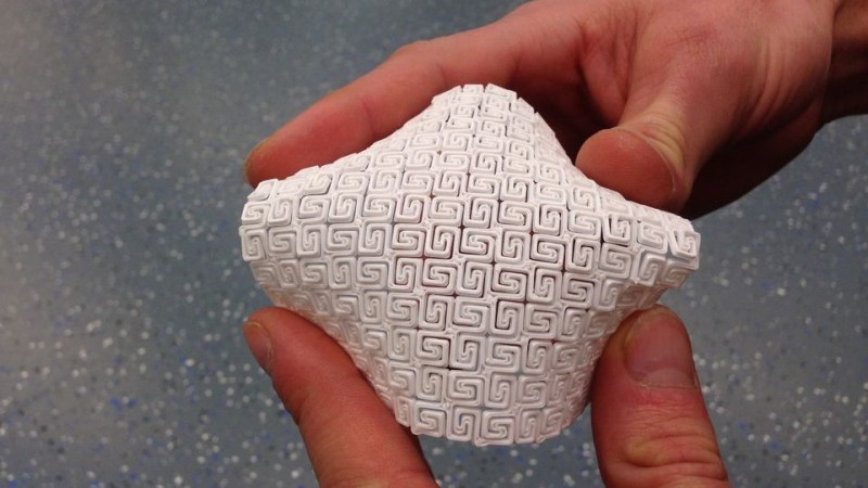
Here’s some interesting work shared by [Ben Kromhout] and [Lukas Lambrichts] on making flexible 3D prints, but not by using flexible filament. After seeing a project where a sheet of plywood was rendered pliable by cutting a pattern out of it – essentially turning the material into a giant kerf bend – they got interested in whether one could 3D print such a thing directly.
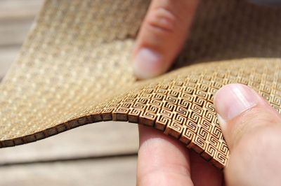
The original project used plywood and a laser cutter and went through many iterations before settling on a rectangular spiral pattern. The results were striking, but the details regarding why the chosen pattern was best were unclear. [Ben] and [Lukas] were interested not just in whether a 3D printer could be used to get a similar result, but also wanted to find out what factors separated success from failure when doing so.
After converting the original project’s rectangular spiral pattern into a 3D model, a quick proof-of-concept showed that three things influenced the flexibility of the end result: the scale of the pattern, the size of the open spaces, and the thickness of the print itself. Early results indicated that the size of the open spaces between the solid elements of the pattern was one of the most important factors; the larger the spacing the better the flexibility. A smaller and denser pattern also helps flexibility, but when 3D printing there is a limit to how small features can be made. If the scale of the pattern is reduced too much, open spaces tend to bridge which is counter-productive.
Kerf bending with laser-cut materials gets some clever results, and it’s interesting to see evidence that the method could cross over to 3D printing, at least in concept.


It also takes a seriously long time to do when vector cutting with a laser but could be sped up if one can print whole layers at once.
Other variants include things like this 3d printed “chainmail”.
https://www.space.com/36719-nasa-chain-mail-space-fabric.html
“takes a seriously long time to do when vector cutting with a laser”
Generalized statement based upon lower power lasers. With a 10″ square of 3mm plywood as the flexible object test, a 75 watt laser can easily cut the pattern faster than a 3D printer could make the same.
Hello, could you share your 3D source files, or at least the STL ?
I think there is no STL because it was being modified for every test anyway so at the time there was no “correct” version. The next best thing is the project page (the first link in the article) has the 2D DWG file of the pattern, along with instructions for turning it into a 3D model in Solidworks and Cura.
That pattern seem quite simple to stamp or mold in large sheets.
What I’d do is just drape the flexible material over a mould… for say example… a chair. Then paint it with resin to hold the form.
Has anyone extended this idea to 3D? A practical realization of a typical crystal lattice model (e.g. https://qph.ec.quoracdn.net/main-qimg-a4cfcbdc3f2a110e32d07233aec2055c ), maybe using torsion springs instead?
I saw this pattern on thingiverse ages ago. I’m glad they discovered it, but it’s an old idea even from a 3d printing perspective.
+1 I was wondering why this seemed to be viewed as something new.
The ancient Greeks were ahead of their time…
Here is my take on this:
https://www.openjscad.org/#https://raw.githubusercontent.com/udif/openjscad-objects/master/flexgrid.jscad
Great work. How difficult would it be to make an OpenSCAD version of that? It’s continued development and produces correct .stl files.
Good luck with that. You are welcomed to try porting it to OpenSCAD, personally I’m not interested in OpenSCAD at all.
I don’t want to start a flame war, but when I started playing with 3D printing not long ago, I looked at both OpenSCAD and OpenJSCAD. For me, choosing one was easy:
OpenJSCAD – using a standard language that can be embedded in a web page and doesn’t require a local client (but you can run locally if you choose so)
OpenSCAD – Using a cusrom language that requires you to install a special client, and you cannot easily share your work on a web page.
Both tools are open soruce so that’s not an issue.
Both projects are continually developed, so that’s also not an issue.
As for STL generation bug , I simply need to file it. It’s not a killer bug that stops me from using the tool. I think it relates to the order of vertices in each triangle or something like that.
Also, OpenJSCAD can read some if not all OpenSCAD scripts (I think it supports older versions of OpenSCAD).
Okay, I taught myself OpenSCAD and wrote a program to make these shapes with programmable sizes, cell complexity, trace width, and gap width. I’ll post it to Thingiverse shortly.
Did you ever end up posting it?