Even if you haven’t used one, you’ve probably seen the numerous projects with the inexpensive RTL-SDR USB dongle. Originally designed for TV use, the dongle is a software defined radio that many have repurposed for a variety of radio hacking projects. However, there’s one small issue. By default, the device only works down to about 50 MHz or so. There are some hacks to change that, but the cleanest way to get operation is to add an upconverter to shift the frequency you want higher. Sounds complicated? [Qrp-Gaijin] shows how to do it with a single transistor. You can see some videos of the results, below.
Actually, [Qrp-Gaijin] built an earlier version but wasn’t satisfied with the performance. He found that his original oscillator was driving an overtone crystal at its fundamental frequency. The device worked, but only because the oscillator was putting out harmonics, including the third harmonic at the actual needed frequency (49.8 MHz).
Changing the oscillator topology did the trick. A tuned circuit prevents the oscillator from having sufficient gain at the fundamental frequency. He did some other tweaks and–according to the post–he still has some future improvements he would like to make.
There have been efforts to improve the RTL-SDR circuitry, too. If you want to see a more complex upconverter, you might want to look at one based on circuit modules.


The problems here:
The rtl stick’s crystal drifts all over the place, the converter’s crystal drifts all over the place.
Solution: Use TCXOs.
Capitalism! https://www.amazon.com/NooElec-NESDR-SMArt-Enclosure-R820T2-Based/dp/B01HA642SW/
People say this, but many a receiver has been built with crystals that aren’t anything special. So why the fuss now? I can see a certain need, but I suspect the idea is getting high travel without the understanding. After all, I’ve seen this in various places, but no explanation travels with it.
Nobody talks about putting a TCXO in a portable shortwave receiver. My tube type 2M FM transceiver back in 1972, industrial surplus, could use crystal ovens, though I never use one. But a car has a very wide temperature range.
Michael
> Nobody talks about putting a TCXO in a portable shortwave receiver. My tube type 2M FM transceiver back in 1972, industrial surplus, could use crystal ovens, though I never use one. But a car has a very wide temperature range.
Your **FM** transceiver, mind you. 2m FM rigs are notoriously bad at frequency accuracy, and it doesn’t matter much for that mode. The deviation from the carrier, which is locked via a slower PLL, is all that matters.
Now, work CW (or even SSB) with a drifting oscillator and you’ll 1) get tired of the signal you’re listening to drifting around, and 2) annoy others as your transmitted signal wanders around.
Nobody was using PSK31 in 1972, either. Or JT65, or any one of several super-narrowband modes on HF that require frequency stability of a few ppm.
Take a look at http://www.rtl-sdr.com then; their $20 metal shielded dongle uses a TCXO and better circuitry than the usual TV USB key.
Wonder if the chips used in cellular picocells may be the next RTL-SDR?
yep, the HackRF uses the MAX2837ETM+, a 4G/WiMAX chipset as a transceiver.
LimeSDR is already being used by telecoms, and will do full duplex LTE cells.
My only annoyance is the lower frequency ports have some impedance matching issues when you dip below 5MHz, and thus will require some balun hacking to get reasonable gains etc. . The 70MHz wide bandwidth, and full duplex 12bit AFE (has wide-band PGAs built-in so an LNA may not even be needed) is mind blowing to think they will improve the current 0.1MHz to 3600MHz coverage limit. People are building dual ported VNAs out of these things too…
I used to calibrate an E4000 dongle ppm with the cell base-station scan, and ppm estimation tool:
sudo apt-get install kalibrate-rtl
The RTL chips are fairly stable once warmed up to operating temperature, and dump1090 works surprisingly well even without a filter.
I cant wait until(and that they do) release the newer SDR military portable radios as surplus, some are good from 27mhz up to or through GHz! What is also cool is at least the pilot’s survival radios do everything from AM aviation voice on civil VHF and mil UHF, secure SAR transponder, GPS, secure satellite text, and EPIRB satellite distress beacon.
Unfortunately the surplus models will likely lack any software due to licensing and fears about crypto stuff leaking.
They might just get crushed :(
The military might cripple them somehow before the release them as surplus.. They do it with field manuals. (Improvised munitions)
It would help to swap the IF and RF ports for additional low frequency coverage. In the current version RF is highpassed by one of mixer transformers.
Thanks very much for the comment! Could you explain a little more how the RF signal is subject to high-pass filtering by the transformer (which components form the filter? Can I see this behavior it in LTspice?), and how swapping IF and RF ports addresses this? I’ve seen that proposed before but I still can’t quite wrap my head around the concept.
Assuming a four diode double balanced mixer, two of the ports are via transformers, so the signals have to pass through the transformer. If the transformers aren’t wound for low frequencies, there will be a frequency limit. And any attempt at better low frequency coverage will likely impact on the high frequency coverage.
The third port is a direct connection to the diodes in the mixer, so it can be used down to DC. Useful if you want to use the mixer as a voltage variable attenuator, or have a very slow modulating frequency, or want to convert a Very Low Frequency up to a higher frequency. For a lot of use, which point won’t matter, but sometimes it does. If you want to use this converter for low frequencies, it will matter.
Michael
Makes sense now — thanks!
About the transformers — they’re 10 turns trifilar on FT50-43 ferrite cores. For conversion of 0-30 MHz up to 50-80 MHz, do you think these transformers are adequate?
It works like this – the center tapped (RF in your schematic) port is actually usable up to 0 Hz, i.e. pure DC. After some thinking it should make sense – it is center-tapped and a symmetric port. The other (IF in your case) is just a winding with one end grounded. It just works as a normal transformer winding, and is always subject to lowpass effect due to combination of source impedance and winding impedance. So the IF port never reaches 0 Hz, the question is only how low you want it to go. The recommended minimum winding inductance is about 4R / (2*pi*f_min), where R is your termination impedance, between 50 and 75 ohm in your case.
From http://toroids.info/FT50-43.php it seems your winding inductance would be around 44 uH, so I would say currently you are highpassing (sorry, mixed it up in the post above) at about 1 MHz. It seems perfectly ok for shortwave, but if you want to go lower, it matters. However, getting close to the heterodyne frequency will be tricky anyway because of leakage and phase noise. I added a LC trap for the leaking LO frequency, it helped a bit, but not completely.
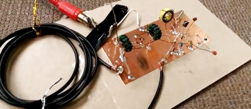
Gaah! Dead bug construction!
My eyes!
For real though, microphonics aside, being able to doodle out a circuit with solder in the same manner you’d draw it on paper is a good skill. Function > form.
Yes, ugly construction is, well, ugly. :) But for prototyping purposes it’s invaluable, especially when you’re not sure if the circuit will even work at all or not. I used to use solderless breadboards for prototyping but I learned not to trust them for RF stuff — too much stray capacitance and long wires that make the circuit unpredictable. It’s ultimately quicker and more reliable just to tack-solder some components on a ground plane and tweak the circuit as I go along. You might have noticed that my ground plane is just a strip of copper tape on a scrap of cardboard — fast, cheap, and stable enough for RF (at HF frequencies, anyway).
When I get around to adding filtering (for FM broadcast frequencies), probably I need to be more careful about shorter lead lengths, neater construction, and maybe shielding. But even in its ugly-constructed state, it’s actually working surprisingly well.
@KarlisG regarding comment from August 9, 2017 at 7:36 am. Quote: “getting close to the heterodyne frequency will be tricky anyway because of leakage and phase noise. I added a LC trap for the leaking LO frequency, it helped a bit, but not completely.”
Regarding leakage from my LO (i.e. imperfect LO-IF port isolation) — will this leakage have any noticeable negative effects at reception from say 500 kHz to 30 MHz (i.e. reception not near the heterodyne frequency)? Practically I don’t need to listen lower than about 500 kHz (AM BCB), but am wondering if an LO LC trap is needed, and if so, why.
On a slightly different topic, someone on another forum said that the dongle’s own LO could leak back out of the dongle’s antenna port and backwards (through my mixer’s IF port) into my mixer, creating unwanted mixing products. Any thoughts on if that’s a problem, and how to address it?
The diode mixer is a very interesting beast with few myths surrounding it. There indeed can happen unwanted mixing, but the simple fact is that it will always happen. Besides f1+f2 and f1-f2 you will have combinations of the kind of n*f1+m*f2, and not just in the IF port. Now if you think of the leakage, I don’t quite buy it, as even if the product n*f1+m*f2 would somehow enter one of the input ports and mix with LO (f2) or any other of the present frequencies, mathematically it would still be of the kind of (n’*f1 + m’*f2), a linear combination. It would definitely affect the spectral _composition_ of the output, but not add new components as such (though they might have been hiding under the noise floor). So by improper termination or LO leakage you are only influencing relative levels of the other, unwanted products which normally have some attenuation. In extreme cases you could start getting unwanted products in your working IF band, and that’s generally just expressed by mixer’s IIP3 rating, but I don’t think it’s a real concern given that your IF processor is a RTL dongle.
Another myth is that somehow diode mixers should be fed pure sine LO and people go lengths to clean it up, only to feed it to a diode mixer which essentially rectifies/chops it up again. The very fact that 3f1+f2 and such products are created is due to this rectifying action (think of the harmonics of a square wave signal). Where LO purity matters is in close to ideal mixers which multiply LO and RF signals. Diode mixers don’t, they pretty much multiply RF with the signum function of LO signal. In short, I wouldn’t worry about all these aspects, they won’t practically change the received signal.
Regarding leakage, you could have trouble with weak signals. Just tune your RTL so that LO hits the reception bandwidth. You will see a huge peak with some falloff around it. You are forced either to lower RTL gain to get this peak under 0 dB (max level of ADC), or else face another reciprocal mixing due to clipping. However, reducing gain means you might lose the weaker signals. Also the smeared falloff around the LO frequency due to combined phase noises of the chain (your crystal oscillator is probably the least to blame, but RTL internal clocks have jitter) will just raise the noise floor and eat up weak signals.
Hope I managed to explain myself.
Regarding LO leakage — or strong signal handling in general by the RTL-SDR — one more basic question, because I don’t know enough about the actual analog radio architecture of the RTL-SDR dongle: Say the dongle is tuned (with no upconverter) to 60 MHz with a sample rate of 2.4 MHz. So what I see on the software waterfall is a 2.4 MHz-wide chunk of spectrum from 58.8 to 61.2 MHz.
Then, say there is a very strong signal just outside the reception bandwidth, say a strong, unmodulated carrier wave at 58.7 MHz. Will this strong signal, just outside the reception bandwidth, negatively affect the receiver in any way? I’m guessing no, and I think that any signals (no matter how strong) that lie outside of the current reception “window” cannot affect/desensitise the RTL-SDR receiver. Is that right? (I’m ignoring the special case of a transmitter operating directly next to the receiver — I’m not talking about that, I’m talking about strong signals from the far field that excite the antenna, but that lie outside of the current reception bandwidth.)
Thanks again for the comments. Diode ring mixers are cool!
I think the RTL receiver architecture is IQ mixer based, with lowpass filtering for extraction (and digitising) of the baseband signal. However, I don’t think these filters are bulletproof. Probably if the strong signal is outside the baseband, it will have way less influence.
Your other projects are cool too, good to see someone is still doing the old-school exploring of RF.
Years ago I made this converter, worked quite well, but still very limited performance for low frequency reception (<500 kHz). It's in Latvian, but I am sure the schematics speaks for itself:
http://www.elfaforums.lv/threads/6606-HF-konvertors-USB-SDR-puļķiem?highlight=konvertors