EE and firmware developer [Enrico] had played with LEDs as a kid, burning out his fair share of them by applying too much current. With the benefit of his firmware chops, he set about creating a board that drives LEDs properly.
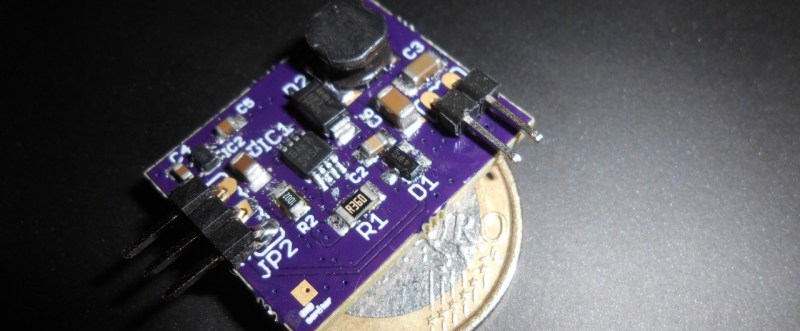
[Enrico]’s project centers around a Texas Instruments LM3405 buck controller. It accepts input voltage from anywhere from 3V to 20V and outputs up to 20V/15W to one or more LEDs. He built a ton of safety features into it like short-circuit and open-circuit immunity, temperature control, and auto-off switching when idle. He also created a LED board to test the maximum efficiency of the driver. It consists of four Luxeon Rebel ES diodes, one each RGB and W. The entire back of the LED board is copper, with a monster heat sink attached.
You can follow along with the Glighter-S project on Hackaday.io, or you can buy one of his boards from his Tindie store.
We’ve covered LED drivers extensively in the past, with posts on a simple 10-watt LED driver and how to design your own LED driver.


When I was a kid (LEDs were fairly new then, and expensive), the only way I could avoid burning them out was by using nearly drained 9V batteries to drive them.
Every other power source caused them to heat up quickly and burn out.
Back then, when I was young and dumb, I couldn’t explain that behavior.
Later I learned about voltage, current, and resistance, and everything became clear.
One missing datapoint is the most interesting for me: What is EMI like from 1 to 1.6 MHz?
I bought some cheap LED drivers off fleabay, and they interfere annoyingly with AM reception.
I built a simple linear constant current source, running two 10W LEDs (=20v) off 24v, giving just 83% efficiency, but no EMI.
Inductor is not shielded and yeah, chip work on 1.6MHz so it will be same noise as you got. Wrap this board into Mu metal foil
I haven’t noticed any issues with some radios, but that does not mean anything. When I get access to some nice instrumentations I can perform some tests. Many thanks for notice this!
Moreover, the EMI could be fine with the board, but then appear with long wires and this, if present, is application dependent.
When time permits, I should try putting the fleabay units in metal enclosures, and fit L or pi filters on input and output, using some of the many ratted 10 and 20 uH toroids in my junkbox, and a few capacitors. That’d disconnect their antennas for a start.
http://flashlightwiki.com/Popular_drivers
So what is the “proper” way to drive an LED? Datasheets typically give the maximum brightness when pulsed at high current for short periods of time at a low duty cycle. I thought that was the “proper” way to drive an LED.
AFAIK, this over-current for short periods of time is related to efficiency: overall you put a very small dutycycle and, despite the higher current, in average you get an equivalent PERCEIVED light higher that nominal current with higher duty cycle, and also lower thermal issues… or more. I saw this used as a trick that works also for red color and is sometimes used in the stop or low-beam rear light of some cars. If you know something else or you can correct me, that would be awesome.
No, sorry, can’t shed anymore light on the subject. The tone of my post might not have suggested it, but I was really curious about the best ways to drive an LED.
Well, in theory the LED is a current device and you should ideally drive it with a current control, and the voltage “just need to be high enough” higher than the LED forward voltage. You vary the current, you directly vary the brightness.