Do you often find yourself needing to make small signs? Perhaps you’re trying to put a notice on the office fridge, but you’re just not in the mood for the usual Comic Sans-on-A4 staple today. A banner of some sort would do the trick, but… a small one, right? [Mike Ingle] has the answer – making mini-banners on old receipt printers.
[Mike] was a fan of Paint Shop in the 1980s, which among other things, enabled the printing of long banners on the popular dot matrix printers of the era. Realising that receipt printers have a similar ability to print on a long continuous strip of paper, he decided to see if it was possible to create small banners using the hardware.
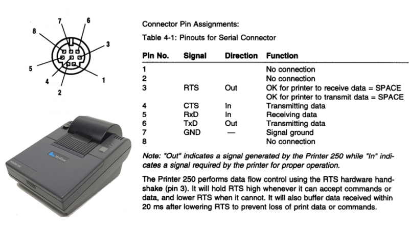
The hack is simple – ImageMagick is used to generate a one-bit black & white bitmap that is then processed with some custom C code to generate something the printer can understand. It’s then a simple matter of hacking up the original RS-232 cable to fit a DB-9 (aka DE-9) connector, and spitting out the instructions over serial.
The mini-banners are cool, and we could imagine having some fun with such a project, using it to print out tweets or putting it into service as a stock ticker. It’s a great example of cleanly interfacing with existing hardware to create something outside of the original design intentions. Such printers are fertile ground for hacks – like this printer that can spit out the US Constitution in 6 seconds flat.


It seems there is an error in that pinout: the pin 4 should have the previous text “OK for printer to transmit data” instead of “Transmitting data”.
The *old* terminology was –
TxD Transmit Data
RxD Receive Data
RTS Request To Send
CTS Clear To Send
DSR Data Set Ready
DTR Data Terminal Ready
The naming convention for RS232 pins went bodged sometimes in the early 80′. the roles of the TxD and Rxd pins was originally reversed for peripheral equipment so that a printers TxD port was for receiving, possible to make cables simpler and useable for daisy chaining when you wanted to attach more equipment to the same port. The standard also specified input tolerance of +/- 12-30V. Try that today and your laptop smokes.
The +/- 12-30V was RS232-S (the “S” being for smoke)
The TxD and RxD reversal was RS232-D (the “D” being for doesn’t work)
More seriously, RS232 was developed for teletype equipment and that is where the odd voltages and terminology comes from.
In the teletype era it was generally One start bit, 5 symbol bits, one and a half stop bits, no parity bit, 75 BAUD (50 bps).
The exchange had a main bus voltage of 48 Volts which is +/- 24 volts and add one volt for margin. Line attenuation (DC resistance) dropping this voltage and right down to +/- 3 Volts was accepted. That gets the original spec of +/- 3 to 25V
The transmit side was a Normally Open (NO) switch that was originally mechanically driven. The receive side was a double action relay where there was one coil to move the actuator left and one coil to move it right. This meant the relay was stable in the left or right position and needed a signal to change. Both coils were connected in a center tap where the incoming signal was applied. The other ends of the coils went to 0V and 48V through current limiting resistors. In those days the bus voltages were called +48V and -48V but the potential difference was only 48V
If you had a moving roll of metalized paper which had a single contact point indicator and you applied +48 Volt to the paper roll and the signal to the contact point indicator as the paper moved you would see a mark for the lower voltages and a space for the higher voltages of the incoming signal.
The first system was Cable Teletype (CTTY) and later there was Radio Teletype (RTTY). You may even remember CTTY from the DOS days.
Probably the modern way to describe the flow control (hand shaking) signals is that many of them were created when modems were connected to standard telephone lines (POTS).
The CTTY TD and RD were renamed TxD and RxD for RTTY and there purpose is obvious.
Clear To Send (CTS) and Request To Send (RTS) were used to control the transfer of data packets.
Data Terminal Ready (DTR) and Data Set Ready (DSR) were used to control the data session.
Carrier Detect (CD) and Ring Indicator (RI) were used to establish the data session.
TL;DR: Damn this coffee is good!
Always enjoy reading your posts RÖB…thanks for taking me to class on RS232. What kind of coffee you got over there?
This could be the most awesome label maker in history.
I think you mean Print Shop, not Paint Shop.
nope, paint shop pro. I had it on the Amiga. it was great. And it could do animation.
“DB-9 (aka DE-9)” It’s not also know as, it *IS* DE-9. Like Han shot. Not first. He shot, Greedo didn’t.
What he said!
https://en.wikipedia.org/wiki/D-subminiature
Those are better than the DIN round ones are.
Can’t believe the Germans ever though those round DIN connectors were the answer.
I wanted to do this to make a robot “flower-girl” that would travel down the aisle at the same speed of the printing process, laying down ASCII flowers as it went. I didn’t have time time (or talent to be honest) so I settled for an RC dump-truck with pedals in the back that my nephew drove instead.