Tesla Coil Uses Vintage Tube

We’ve seen a fair amount of Tesla coil builds, but ones using vacuum tubes are few and far between. Maybe it’s the lack of availability of high power tubes, or a lack of experience working with them among the younger crop of hackers. [Radu Motisan] built a vacuum tube Tesla coil several years back, and only just managed to tip us off recently. Considering it was his first rodeo with vacuum tubes, he seems to have done pretty well — not only did he get good results, he also managed to learn a lot in the process.

His design is based around a GI-30 medium power dual tetrode. The circuit is a classical Armstrong oscillator with very few parts and ought to be easy to build if you can lay your hands on the tricky parts. The high voltage capacitors may need some scrounging. And of course, one needs to hand-wind the three coils that make up the output transformer.

Getting the turns ratios of the coils right is quite critical in obtaining proper power transfer to the output. This required a fair amount of trial error before [Radu] could get it right.

The use of a 20W fluorescent tubelight ballast to limit the inrush current is a pretty nice idea to prevent nuisance tripping of the breakers. If you’d like to try making one of your own, head over to his blog post where you will find pictures documenting his build in detail. If you do decide to make one, be extremely careful — this circuit has lethal high voltages in addition to the obvious ones, since it operates directly from 220 V utility supply.

Continue reading “Tesla Coil Uses Vintage Tube”

Winch Bot Records Hacks And Cats

Some people are better than others when it comes to documenting their hacks. Some people, like [Micah Elizabeth Scott], aka [scanlime], set the gold standard with their recordings. Hacking sessions with the Winch Bot have been streamed regularly throughout the build and this is going to lead to a stacking effect in her next projects because the Winch Bot was designed to record hacking sessions. Hacking video inception anyone? Her Winch Bot summary video is after the break.

The first part of this build, which she calls the Tuco Flyer, was [Micah Elizabeth Scott]’s camera gimbal hack which we already covered and is a wonderful learning experience in itself. She refers to the gimbal portion as the “flyer” since it can move around. The Winch Bot contains the stationary parts of the Tuco Flyer and control where the camera will be in the room.

Continue reading “Winch Bot Records Hacks And Cats”

Remote Controlled Streaming Speakers

For want of a better use of a spare Raspberry Pi Zero W and a set of LogitechZ-680 surround sound speakers, [Andre van Kammen] hacked them together to make them stream music playing from his phone.

It was stumbling across the Pi Music Box distribution that really got the ball rolling, and the purchase of a pHAT DAC laid the foundation. Cracking open the speakers’ controller case, [Kammen] was able to get 5V of power off some terminals even when the speakers were on standby — awesome! — which the Pi could use. Power and volume are controlled via the Pi’s GPIO pins with a diode to drop the voltage and prevent shorts.

Now, how to tell whether the speakers are on or off? Well, a pin on the display connector changes to 4.3V when it’s on, so wiring a 10k resistor and a diode to said pin is a hackable solution. Finishing off the wired connections, it proved possible to cram the pHAT DAC inside the controller case with the GPIO header sticking out the back to mount the Pi upon with no other external wires — double awesome!

Continue reading “Remote Controlled Streaming Speakers”

Battery Management Module Hacked For Lithium-Iron Battery Bank

In a departure from his usual repair and tear down fare, [Kerry Wong] has set out on a long-term project — building a whole-house battery bank. From the first look at the project, this will be one to watch.

To be fair, [Kerry] gave us a tease at this project a few months back with his DIY spot welder for battery tabs. Since then, he appears to have made a few crucial design decisions, not least of which is battery chemistry. Most battery banks designed for an inverter with enough power to run household appliances rely on lead-acid batteries, although lithium-ion has certainly made some inroads. [Kerry] is looking to run a fairly small 1000-watt inverter, and his analysis led him to lithium-iron cells. The video below shows what happens when an eBay pack of 80 32650 LiFePo4 cells meets his spot welder. But then the problem becomes one of sourcing a battery management system that’s up to the charge and discharge specs of his 4s battery pack. We won’t spoil the surprise for you, but suffice it to say that [Kerry] really lucked out that only minimal modifications were needed for his $9 off-the-shelf BMS module.

We’re looking forward to seeing where this build goes, not least because we’d like to build something similar too. For a more traditional AGM-based battery bank, check out this nicely-engineered solar-charged system.

Continue reading “Battery Management Module Hacked For Lithium-Iron Battery Bank”

Hackaday Prize Entry: An Optical Power Meter

This is the type of crowd that’s famous for building their own test equipment. If you need a way to program a flash chip, don’t go out and buy one — you can just build one. Need a spectrum analyzer? You can build that out of copper clad board. For his Hackaday Prize entry, [oakkar7] is building an optical power meter, capable enough to do futzy fiber work, but still completely DIY.

When you get into networking and telecom connections that don’t begin with the letters ‘RJ’, you start to stumble upon SPF transceivers. These ‘small form factor pluggable’ devices are little modular transceivers capable of handling fiber, Gigabit Ethernet, and other slightly weirder bit pipes. When used with fiber, they can measure optical power in dBm and watts, and can be debugged by a UART.

[oakkar]’s optical power meter uses these SPF transceivers, tied together with a fairly simple circuit consisting of an Arduino, a few tact switches, a Nokia LCD, and an FTDI UART. The key in tying all of this together is an Arduino library for SPF and DDM (Digital Diagnostics Monitoring), giving the user access to all the configuration bits in these transceivers.

While the circuit is simple enough to be built on a piece of perfboard, [oakkar] really knocked it out of the park with the enclosure on this one. With just a little bit of laser cut acrylic and a few standoffs, [oakkar] has a device that actually looks professional, and has most of the capabilities of fancier, more expensive tools.

What’s The Best Way To Learn Electronics?

What’s the best way to learn electronics? It’s a pithy question to ask a Hackaday audience, most of whom are at least conversant in the field already. Those who already have learned often have just their own perspective to draw upon—how they themselves learned. Some of you may have taught others. I want to explore what works and what doesn’t.

Hobbyists Learn Differently Than Students

One thing I can say straight off is that students learn differently than people who learn at home. Hobbyists have the advantage of actually being interested, which is a quality a student may not enjoy. People have been teaching themselves electronics since the beginning, with analog projects–Heathkit models, BEAM robots, and ham radio sets–evolving into purely digital projects.

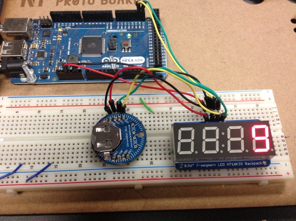
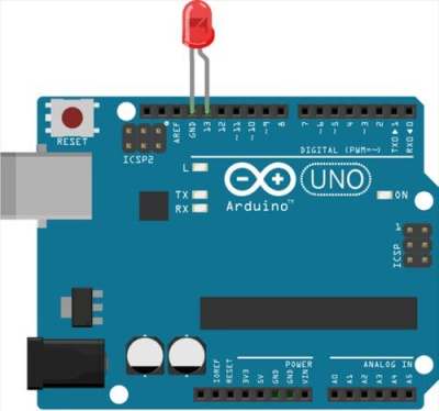
Let’s face it, Arduinos lower the bar like nothing else. There’s a reason why the Blink sketch has become the equivalent to “Hello World”. Dirt cheap and easily configured microcontrollers combined with breakout boards make it easy for anyone to participate.

However, ask any true EE and that person will tell you that following wiring diagrams and plugging in sensor boards from Sparkfun only teaches so much. You don’t bone up on terms like hysteresis or bias by building something from uCs and breakout boards. But do you need to? If you are truly interested in electronics and learn by making those Adafruit or Sparkfun projects, sooner or later you’ll want to make your own breakout boards. You’ll learn how to design your own circuit boards and figure out why things work and why they don’t. I don’t need to tell you the Internet has all the answers a neophyte needs–but the interest has to be there in the first place.

What’s the Best Way to Learn in the Classroom?

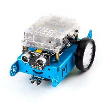
There is a product category within robotics kits that consists of “educational rovers” designed to be purchased in group lots by teachers so that each student or small group gets one. These rovers are either pre-built or mostly built—sure, you get to screw in motor mounts, but all the circuit boards are already soldered up for you, surface mount, no less. They come pre-configured for a variety of simple tasks like line following and obstacle avoidance. The Makeblock mBot is an example.

I think it’s part of that whole “learn coding” initiative, where the idea is to minimize the assembly in order to maximize the coding time. Insofar as soldering together a kit of through-hole components teaches about electronics, these bots mostly don’t do it. By all appearances, if there is a best way to learn electronics, this an’t it. However, regardless of what kind of project the teacher puts in front of the student, it still has to generate some sort of passion. What those robots provide is a moment of coolness that ignites the firestorm of interest.

I once led a soldering class that used Blinky Grids by Wayne and Layne as the focus. This is a fantastic kit that guides you through building a small LED matrix. It’s particularly cool because it can be programmed over a computer monitor with light sensors interacting with white and black squares on the company’s web site. When my students finished their grids, they all worked and had unique messages scrolling through. Now, that is a payoff. I’m not saying that any of those folks became hardware hackers as a result of my class, but it beat the hell out of a Christmas tree, am I right?

Getting back to that rover, what must be acknowledged is that the rover itself is the payoff, and that’s only as far as it goes if everyone loses interest. However, a lot of those rovers have expansion possibilities like bolting on another sensor or changing the method of programming–for instance, the mBot has both a graphic programming interface and can also be reflashed with a regular old Arduino bootloader.

Readers, share in comments your own perspective. How did you learn? How would you teach others?
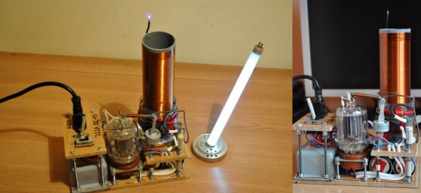
Hacked Headset Brings VR To The Commodore 64

The venerable Commodore 64 got a lot of people started in computers, and a hard core of aficionados keeps the platform very much alive to this day. But a C64 just doesn’t have the horsepower to do anything more than some retro 8-bit graphics games, right?

Not if [jim_64] has anything to say about it. He’s created a pair of virtual-reality goggles for the C64, and the results are pretty neat. Calling them VR is a bit of a stretch, since that would imply the headset is capable of sensing the wearer’s movements, which it’s not. With just a small LCD screen tucked into the slot normally occupied by a smartphone in the cheap VR goggles [jim64] used as a foundation for his build, this is really more of a 3D wearable display — so far. The display brings 3D-graphics to the C64, at least for the “Street Defender” game that [jim64] authored, a demo of which can be seen below. We’ll bet position sensing could be built into the goggles to control the game too. Even then it won’t be quite the immersive (and oft-times nauseating) experience that VR has become, but for a 35-year old platform, it’s not too shabby.

Looking for more C64 love? We’ve got a million of ’em — case mods, C64 laptops, tablets, even CPU upgrades.

Continue reading “Hacked Headset Brings VR To The Commodore 64”