After a couple of millennia of fiddling with gears, you’d think there wouldn’t be much new ground to explore in the field of power transmission. And then you see something like an infinitely variable transmission built from nested pulleys, and you realize there’s always room for improvement.
The electric motors generally used in robotics can be extremely efficient, often topping 90% efficiency at high speed and low torque. Slap on a traditional fixed-ratio gearbox, or change the input speed, and efficiency is lost. An infinitely variable transmission, like [Alexander Kernbaum]’s cleverly named Inception Drive, allows the motor to stay at peak efficiency while smoothly changing the gear ratio through a wide range.
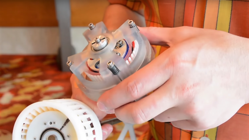
The mechanism takes a bit of thought to fully grok, but it basically uses a pair of split pulleys with variable spacing. The input shaft rotates the inner pulley eccentrically, which effectively “walks” a wide V-belt around a fixed outer pulley. This drives the inner pulley at a ratio depending on the spacing of the pulley halves; the transmission can shift smoothly from forward to reverse and even keep itself in neutral. The video below will help you get your head around it.
We’ve seen a couple of innovative transmissions around here lately; some, like this strain-wave gear and this planetary gearbox, are amenable to 3D printing. Looks like the Inception Drive could be printed too. Hackers, start your printers and see what this drive can do.
Thanks for the tip, [anfegori91].


It’s an interesting hybrid of CVT and harmonic drive.
Wonder what the durability is?
If I understand correctly, it’s still friction based, so the power would be limited to prevent excessive heating. Also, if the gear ratio approaches zero, the output torque would approach infinity; very few shafts can handle infinite torque.
Servo drives can already very efficiently provide regenerative braking, assuming there is sufficient buffer capacity to store the energy, so I don’t think this will make cyclic motions more efficient. Also, with proper current and speed control, drives can be safe for human interaction; having a CVT that slows down a shaft to a low RPM in order to be safe, would provide a huge torque, making it potentially dangerous again.
Don’t get me wrong, I think it’s an interesting concept that might have some legitimate applications, but I don’t think those examples are. Instead, a recurring problem with electric drives is the available peak torque at low RPM and the maximum RPM that can be reached at a given bus voltage. BLDC motors, for example, have a nearly flat torque curve, all the way up to the bus voltage speed limit. With such CVT, this torque curve can instead approximate a constant power curve, where the torque at low speeds is many times larger, mostly limited by the strength of the CVT.
The question then becomes, how strong and efficient can they actually make it?
The problem with VFD directly driving a motor is that near zero rpm producing torque is terribly inefficient, and likewise regenerative braking starts to consume energy rather than collecting it because it takes power to provide the magnetic excitation to make the motor act as a generator.
The CVT bypasses this mechanically by allowing the motor to spin at a constant RPM in the same direction through the whole process, so it can maintain efficiency both in regeneration as it’s being backdriven by the transmission at constant RPM, and then as the load direction changes by not having to slow down.
>”having a CVT that slows down a shaft to a low RPM in order to be safe, would provide a huge torque, making it potentially dangerous again.”
Suppose you have a synchronous AC motor being fed a constant frequency. The amount of torque drawn from the motor depends on how fast you change the transmission ratio i.e. how fast you try to make the mechanism accelerate. The motor tends to spin at a constant RPM, so it applies torque only as necessary to meet the new output speed you’re trying to accomplish, which is under your control to choose. If your sensors detect unsafe torques, you can slow down – likewise if you don’t have a force sensor on your actuator then the VFD drive becomes equally unsafe because it will apply more and more torque to get the actuator to speed up just the same.
Pretty much what I was thinking. As demonstrated it seems to have an extremely narrow useful operating range because vibration limits top speed but you don’t have enough rigidity through the belt for low-speed applications either.
this is great!
That is brilliant, as he points out at the end of the video, a robot needs only one large drive motor and power shaft per limb then the actuation of each joint is determined by a smaller motor controlling a IVT there.
This can also be done with a differential. As 2 input one output, one driven by a heavy motor. the other by a small motor.
Isn’t the problem with that model that the small motor ends up having to produce as much torque as the large one for some ratios? There are any number of “infinitely variable geared transmission” designs which boil down to two motors driving a differential: looks great on a model under zero load but as soon as you try to make it do work the small motor lets the magic smoke out because it’s being overloaded.
Well, they managed to make the two-motors-and-a-differential scheme work OK for propelling the vast number of Toyota Priuses you see zipping their way around the roads so presumably there are some configurations and applications for which that works.
The gist I got from this article was that they aren’t saying this will replace all transmissions but rather saying this, if they can make it rugged, will be a better compromise between efficiency, maximum power, and weight for extremely space constrained applications (like at the wrist of a robot arm rather than to drive a car).
There’s three motors in the prius, one being the engine. Both electric motors can apply torque to the differential when high torque is needed.
Yep. While a geared CVT isn’t impossible in principle the same way that a perpetual motion machine is, it’s a good bet for almost the same reasons that anyone claiming to have one is wrong. I had to debunk one, and exactly as you said- at certain ratios, the ‘small motor’ had to produce more torque than the big one in order to keep the gears in place.
To be fair, I haven’t looked at this one yet… but I have a good idea what a thorough analysis would show.
I bet there is a better way to do this, but the person who figures it out deserves a nobel prize.
Can one get a nobel prize in mechanical engineering?
Not sure. But I’m down to change my name to Nobel and hand out a prize.
Ha!
There are several versions of just this sort of variable pulley mechanism in Gardner Hiscox’s book ‘1800 Mechanical movements, devices and appliances’…originally published in 1900 or so….
That’s a neat book. Things 1321-1325 are variable speed transmissions but they don’t have the nested configuration that is the new invention.
Reminds me of the d-drive transmission system in that its variable
I wonder what the efficiency of the gears itself is. Friction based CVT’s are often not very efficient. So they mostly increase the overall efficiency of a heat engine based system (because of the rpm/torque limitations, but electric motors have a much wider power/torque range over rpm’s. That’s the reason most EV’s don’t have a shiftable gearbox.
It’s essentially a brilliant reinvention of the Saab’s belt CVT from the 1980’s.
It was a bit earlier than the 80’s , try the 50’s -> https://en.wikipedia.org/wiki/DAF_600
Which of course wasn’t the first time that technique was used.
Once again the ‘re invention’ of previous technology.
Give him a trophy.
that really looks like a variable harmonic drive to be honest.
But it isn’t quite because it is friction based, as far as I know harmonic drives are more suitable to high forces because they have actual gears which aren’t easily variable. It is nested similarly, but I don’t think it’s a harmonic drive.
Forget robots, I wanna see how this works out on bicycles! ;)
I can’t believe it would survive very long.
Especially the reverse gear
I have a few common misconceptions that really eat at me. Misuse of “inception” is one of them.
Thanks to the movie “Inception”, people have this wonky idea that inception involves things nested within things. This led to the popular “something-ception” memes. In the movie, they explain what inception is quite clearly, that it is the planting of an idea in someone’s dreams and memories so that they believe it was their idea in the first place, that the inception of the idea was within them.
Coincidentally, this is a correct usage of the term based on the dictionary definition.
Oy.
I swear that is the shirt my mother bought me for 7th grade in 1964. (Cool drive though.)
Good job at color-blending with the carpet.
oh and cool drive!
Why would you need CVTs in robots when you are using a electric motor ?
I think I’m missing something …
But can it be back-driven?
This drive will be difficult to keep balanced. Changing the gear ratio affects the shape of the belt and how much of the belt is moving eccentrically.
Perhaps the drive can be doubled up with the eccentric movements 180 degrees out of phase. Similar to some cycloidal gearboxes.
“Grok..” I got it. Makes me want to revisit my fully toothed gear CVT now that I have designed and built a couple 3D printers.