When it comes to transmissions, a geared continuously-variable transmission (CVT) is a bit of a holy grail. CVTs allow smooth on-the-fly adjustment of gear ratios to maintain a target speed or power requirement, but sacrifice transmission efficiency in the process. Geared transmissions are more efficient, but shift gear ratios only in discrete steps. A geared CVT would hit all the bases, but most CVTs are belt drives. What would a geared one even look like? No need to wonder, you can see one for yourself. Don’t miss the two videos embedded below the page break.
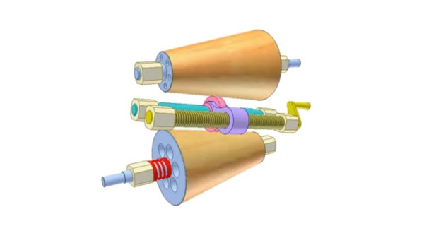
The design is called the RatioZero and it’s reminiscent of a planetary gearbox, but with some changes. Here’s how the most visible part works: the outer ring is the input and the inner ring is the output. The three small gears inside the inner ring work a bit like relay runners in that each one takes a turn transferring power before “handing off” to the next. The end result is a smooth, stepless adjustment of gear ratios with the best of both worlds. Toothed gears maximize transmission efficiency while the continuously-variable gear ratio allows maximizing engine efficiency.
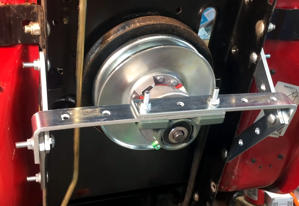
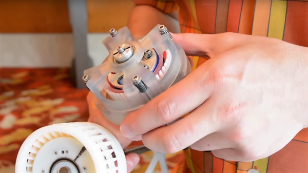
There are plenty of animations of how the system works but we think the clearest demonstration comes from [driving 4 answers] with a video of a prototype, which is embedded below. It’s a great video, and the demo begins at 8:54 if you want to skip straight to that part.
One may think of motors and gearboxes are a solved problem since they have been around for so long, but the opportunities to improve are ongoing and numerous. Even EV motors have a lot of room for improvement, chief among them being breaking up with rare earth elements while maintaining performance and efficiency.
Continue reading “Behold A Geared, Continuously Variable Transmission”