Stepper motors are a staple in all sorts of projects, but it’s often the case that a gearbox is needed, especially for applications like the linear drives in CNC machines and 3D printers. In those mechanisms, a high-torque, low backlash gearbox might be just the thing, and a 3D printable split planetary harmonic drive for the popular NEMA 17 motors would be even better.
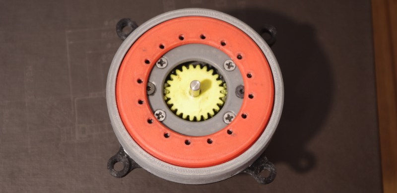
Right up front, we’ll say that we’re skeptical that any plastic gearbox can stay as backlash free as [SirekSBurom] claims his creation is. But we can see the benefits of the design, and it has some nice features. First off, of course, is that it’s entirely 3D printed, except for a few screws. That it mates perfectly with a NEMA 17 motor is a really nice feature, too, and with the design up on Thingiverse it shouldn’t be too tough to scale it up and down accordingly. The videos below show you the theory: the stepper drives a sun gear with two planet gears orbiting, each of which engages a fixed ring of 56 teeth, and an output ring of 58 teeth. Each revolution of the planets around the fixed ring rotates the output ring by one tooth, leading to almost 100:1 reduction.
We think the ‘harmonic’ designation on this gearbox is a little of a misnomer, since the defining feature of a harmonic drive seems to be the periodic deformation of a flex spline, as we saw in this 3D-printed strain wave gear. But we see the resemblance to a harmonic drive, and we’ll admit this beastie is a little hard to hang a name tag on. Whatever you call it, it’s pretty cool and could be a handy tool for all kinds of builds.


I’m fairly certain that the term you are looking for is epicyclic.
Epicyclic is the term to use, but it doesn’t fully descirbe the functioning principle in this case.
Def Epicyclic. See Figure 1-C (http://www.akgears.com/pdf/High%20Gear%20Ratio%20Epicyclic%20Drives%20Analysis.pdf)
This is exactly describing this system. The word i’ve been missing is compound.
Thanks for the paper, it would have saved me some time of experimentally working out the ratio formula.
No prob. This is actually really cool stuff! I kept the paper so I could 3D print one. This guy beat me to it.:)
https://www.dropbox.com/s/z18zuqvqtbldzcj/r444.png
You can definitely see the resemblance to the ones in the paper :)
Just wanted to say that i’m working on a new ‘sturdy’ version which incorporates integrated PTFE tube sliding surfaces. I can’t really release the design yet as my printer is experiencing some serious downtime, and i can’t test the design (althought i’m pretty confident it will work as expected on the first try). Anyways, here’s a screenshot of a semi-exploded assembly. You will notice that i added a third planet gear; this changes the ratio formula a bit, so this one will be a 76:1 reducer. Also i set the requirement of IP63 or IP64 to be met, but i’m not sure how will that turn out.
https://www.dropbox.com/s/ngm6xzvefaubcgm/sr.png
looks great, it would definitely benefit from multiple materials, nylon or some of the PET materials might be well suited, they are after all used in gears all over the place to begin with.
PTFE is a nice idea for reducing sliding friction.
A compound planetary gearbox. The output ratio can even be negative if the output gear has less teeth than the fixed annulus. Check out this one: http://www.zakgear.com/Power_Hinge.html
It IS indeed planetary harmonic drive. Planetary gears are used instead of strain gear, but they are not driving planet carrier. Please look at second video. Upper lid has less teeth than lower ring and those gears are only used as a wave generator.
I don’t see what’s the wave generator and nothing is straining, The upper lid just has different number of teeth. It appears to be a clever epicyclic drive that has two ring gears with different gearing.
Planets are non-straining wave generator here.
Actually, it IS a harmonic drive. Watch the second video. The two ring gears have different numbers of teeth, so that when one is held stationary, you get a high effective gear ratio to the other one – the one that is removed so you can see inside. Deformation of one of the elements is just one way to make a harmonic drive.
I have seen this layout before (two rings with different teeth counts driven by the same set of planets), NASA even patented it if you phase shift the planets teeth:
https://technology.nasa.gov//t2media/tops/pdf/GSC-TOPS-12.pdf
They have a full paper showing how it can be made zero backlash (you make the planetary gears helical and key one set with a spring washer), as well as all the math for calculating how to make the fit and the ratios.
It is not a harmonic drive, just a variation of regular compound planetary gearboxes (which can have a fixed ring and output ring).
I’m having trouble digging up the full papers but here are some notes:
https://ntrs.nasa.gov/search.jsp?R=20100011221
https://ntrs.nasa.gov/search.jsp?R=20090043144
You seem to be using the same tooth profile (in fact, exact same gears) for both planetary gears even though they mesh with rings of different teeth numbers. You can alter the tooth profile to achieve perfect rolling contact and phase shift the tooth offsets to allow any number of planets (as described in the papers).
Note this is all stuff from 2007.
Thanks for the papers and info, it should be really useful!
I’m using the same gears to roll on both rings, but the module of the output ring tooth profile is adjusted in a way that both ring root diameters are aproximately the same, and because of the small adjustment of the module (0.05) i decided to use same gears as i evaluated that it wouldn’t cause any significant reduction of performance and/or increase in wear.
From what i’ve been able to find, this is the only difference between my design and already existing systems. Of course, I can’t claim that no one else came up with an exact same design as I did.
Thanks for the notes once again, i’ll study them and see if I can improve on the design in any way.
This has the most detail, although something went wrong with the drawings and you need to zoom in:
http://ipp.gsfc.nasa.gov/downloads/featured_technologies/mechanical_technologies/14207_half_gearbearingpresndes2003.pdf
The anti backlash mechanism on page 20 is very challenging to manufacture traditionally but should print easily. You can also eliminate the planet carrier by borrowing some of the other ideas.
That’s actually really interesting, a quick read of the presentation just gave me an idea on how to preload the rings so they would stay in place without even touching each other.
I must admit it’s kinda hard for me to understand all of the things in those papers because i’m not that familiar with the nomenclature that’s used there. I will definitely go through these more thoroughly when i have the time, hopefully i’ll have an improved design when i do. Thanks again!
Oh, and i can get away with not using the carrier at all, at least i got away with it in the brief testing period (you can see it in the second video), i presumed that the whole assembly would be sturdier with the carrier incorporated. I guess i’ll have to go through more testing and few iterations of the design to be certain.
BrightBlueJim that just makes it a differential drive, like the Chinese Windlass. A harmonic drive has a strain wave gear (SWG).
Very cool, I tried to build 3d printed harmonic drives but I never get rid of the wobble with the flexible gear, very nice design, well done.
That exact wobble you’re talking about is what motivated me to design this. I had some limited success with experimental ‘true’ harmoic drives. By success i mean that all i was able to acomplish is to make a decent model which demonstrates the working principle of the drive.
You can check it out here: http://www.thingiverse.com/thing:2107873
I may pursue a true harmonic drive design, but it depends on the outcome of my current project.
I’ve seen very similar in car mirrors with motorized adjustment.
For a picture, see https://en.wikipedia.org/wiki/Epicyclic_gearing#Gallery
Interesting, but what about the expected life of a3D printed plastic gear? Am I wrong or it should be even shorter than a molded gear? 3D printing is neat but I’m still skeptical about the strength of pieces made of thin layers bonded only on their surface.
Honestly it depends on the load and the quality of the print. Most of the strain on a gear is at the surface, that’s why it’s possible to remove so much of the center material. I would imagine that this is being used more for speed reduction and an increase in step precision (each step makes a smaller change allowing more control albeit at a slower speed) rather than torque multiplication. It’s always possible to laser cut them out of delrin too, or maybe CNC them out of brass or cast iron, unless it’s dependent on flexing the gears for some reason.
I actually stress-tested this on a 12 hour run, and the whole assembly performed as intended, and there is almost no wear on the gears. I still wouldn’t recommend to run this dry, as friction can be a problem, especially if it’s fresh out of the printer. If you use a lot of grease, and move moderate loads with this (somewhere around 20-40 Nm) it should last a relatively long time, at least from my experience.
Bravo for BurekSaSirom. How can this be used to produce burek, or sir? :)
Working on a 2 stage Cycloid drive for nema 17…I’ll send it in when im done. On the subject of wear, and backlash, industrial use study seems to show more promise in 3d printed cycloid drive (over planetary or harmonic drives) due to their profile.
For the RepRap project, that would eliminate the need for a stepper driver with micro-stepping. Simply use a higher gear ratio with a 3D-printed stepper motor that’s driven by four transistors.
Although I’m a card-carrying hacker, I’ve always been pretty meh on 3-D printing… but I have to say that this is the first application that truly impressed me. Bravo for that, and for the impressive engineering.
whoa now, lets not praise 3D printers too much here. You could also do this with a laser cutter
Watching those videos I was thinking, if you had a 60:1 speed reduction between drive and output you’d have a clock dial mechanism.
This is not a harmonic drive, split annulus planetary gear set. The split is between the two ring gears (annulus). It is, effectively, using the planetary carrier (which doesn’t exist) as an output from one set and as an input for the other. The closer the two ratios of the two gear systems, the higher the gear ratio. If the gear ratios were identical, the gears wouldn’t move at all.
:cough: https://www.youtube.com/watch?v=kYmUJVE6Vo0
This gear configuration is patented. Please remove it and do not use it in any products.
Sjkochan: The essence of the patent process is that a) you get to have exclusive use of your invention for a period of time, but b) you have to disclose how it works. Therefore there is no cause to “remove it”, and unless you are the holder of the patent, you have no say over where it can be used. Thank you for your input.
I am the holder of the patent.
My Patent is # US 8,591,367 B2 — Kochan — Nov 26, 2013
Please note below that making it without authority and also “inducing infringement” which means encouraging others to make it is infringing.
1. U.S. Code › Title 35 › Part III › Chapter 28 › § 271
35 U.S. Code § 271 – Infringement of patent
(a)
Except as otherwise provided in this title, whoever without authority makes, uses, offers to sell, or sells any patented invention, within the United States or imports into the United States any patented invention during the term of the patent therefor, infringes the patent.
(b)
Whoever actively induces infringement of a patent shall be liable as an infringer.
Please remove this.
thank you
To avoid infringement, people just need to use a different pitch set of spur gears like the NASA design from 2003.
You need to be careful, as they could file a $2k Patent-expunge proceeding asserting US8591367 is functionally equivalent to prior art.
* it is similar as the NASA gear pitch difference will fall within the mechanical backlash if the tooth count is close, and thus US8591367 will fail the Novel criterion after public review.
Your patent looks like it was filed prior to the first-to-register rules came into effect in the US, and holders don’t get to control its application outside of a commercial context once published in the public domain. You may go after companies attempting to sell the design though, but soon you may have to prove financial losses if you are not actively selling/manufacturing the design.
I have 5 patents approved, drafted several dozen others for companies, and would be embarrassed to admit reinventing the wheel.
Good luck ;-)
All right then, I won’t make one of these. Still, showing how something works is not inducement, especially now that they’ve published your comment.
Good fortune to you.
People get to study your patent, that’s the point of the patenting system. Republishing a grant of the US government is not illegal or unethical. In fact, having notice of your patent allows makers to implement their designs without violating your patent, comments to the contrary not withstanding. If your invention inspires someone to find a better design, or a close approximation of your invention that does not “read on” your invention, then the patent system has worked to everyone’s advantage. You are entitled to what you bargained for; and you knowingly surrendered any right to ;publish. As far as using it in products, perhaps a better approach would be to acknowledge to yourself that you don’t get to actually prevent anyone from creating a copy to study or use as a model. If someone commercially produces a product that infringes on your patent, go get them. If someone designs a workaround to your invention that has desired performance characteristics but doesn’t actually violate your patent, then they get to do that.
Id like to know the torque , I am trying to make this
https://www.behance.net/gallery/1902587/Cyclus-Step
the motor on average works at 1000 rpm,
I have used a single stage planetary gearbox (like yours shows) and they all required very little torque to move ( they were 10 to 1)
I wonder if yours can be moved easily with a persons hand
I also wonder if you can put 2 stages meaning 10,000 to 1
or 3 stages meaning 1 million to 1
I have moved a 2 stage planetary gears with my hand (at about 15lbs per inch of torque)
and I moved a 3 stage planetary gears with my hand but the 3 stage had about 25 lbs per inch of torque
( the spring has 30lbs per inch of torque)
If yours could be made to move at 1 million to 1 ( that would be a dream I had)
or even 2 stage of 10,000 to 1
and finally I wonder if ceramic gears inside the planetary gears would make it move easier
thank you for your amazing piece
Hello i can easy design make it about 3000 to 1 if you want with only 2 stage
I had no idea that gearboxes are needed for CNC machines. I am starting to get into machining myself. Maybe I can get some custom parts made to fit whatever machine I get so it will run better.