Even the staunchest 3D printing supporter would have to concede that in general, the greatest strength of 3D printing is not in the production of final parts, but in prototyping. Sure you can make functional prints, as the pages of this site will attest; but few would argue that you wouldn’t be better off getting your design cut out of metal or injection molded if you planned on putting the part into service over the long term. Especially if the part was to be subjected to rough service in an industrial setting.
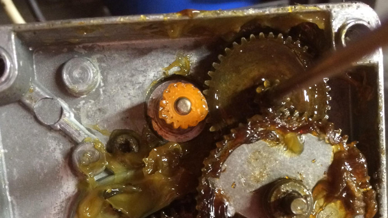
While that’s valid advice, it certainly isn’t the definitive word on the issue. Just because a part is printed in plastic on a desktop 3D printer doesn’t necessarily mean it can’t be put into real service, at least for as long as it takes to get proper replacement parts. A recent success story from [bloomautomatic] serves as a perfect example, when one of the gears in his MIG welder split, he decided to try and print up a replacement in PLA while he waited for the nylon gear to get shipped out to him. Fast forward seven months and approximately 80,000 welds later, and [bloomautomatic] reports it’s finally time to install those replacement gears he ordered.
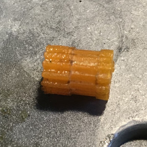 In the pictures [bloomautomatic] posted you can see the printed gear finally wore down to the point the teeth were essentially gone where they meshed with their metal counterparts. To those wondering why the gear was plastic to begin with, [bloomautomatic] explains that it’s intended to be a sacrificial gear that will give way instead of destroying the entire gearbox in the event of a jam. According to the original post he made when he installed the replacement gear, the part was printed in Folgertech PLA on a Monoprice Select Mini. There’s no mention of infill percentage, but with such a small part most slicers would likely have made it essentially solid to begin with.
While surviving seven tortuous months inside of the welder is no small feat, we wonder if hardier PLA formulations, treatment of the part post-printing, or even casting it in a different material couldn’t have turned this temporary part into a permanent replacement.


Something i wish was possible.
using electroplating to reinforce prints.
For gears you can simply mould them in 2k silicone and then cast new ones from 2K PUR plus some fibers. Done in under 1hr (print in this size 5min, dental silicone ~20min, PUR 20 minutes plus some time to harden further). All ready to use in about 3hrs to a day.
Or simply 3D print a single use mold for the piece you needed.
Glass fiber or Metal flake filled two-part 24hour epoxy can be very strong, and is resistant to most oils.
Remember that Curing time is different from Drying time, and some materials can take several weeks to reach full strength.
Anecdotally, I have observed that generally the faster something sets, the weaker it becomes both in rigidity and wear properties.
That’s more than an anecdote. Just about all quick set epoxies are weaker than slow set. They’re also more brittle than slow set. Depending on the brand and pot life time difference (1h vs 24h) the increase in strength may not be a whole lot.
It’s entirely possible you will probably want an electroless nickel process however and then finish with electroplating for thicker coatings.
Painting with graphite and electroplating is not really a solution. There are commercial processes you can acquire that will be your best bet as rolling your own solutions is wrought with trial and error and getting the reductants needed will not be possible without chemical licencing.
You can use 0.1 molar stannous chloride and 0.1 molar palladium chloride to activate the surface of the plastic then use a kit like this and it SHOULD work. https://www.caswellplating.com/electroplating-anodizing/nickel-plating-kits/electroless-nickel-plating-kits/electroless-nickel-standard-kit-10-pint.html
Been done
It is totally possible. The 3D Printing Today Show guys did it using conductive copper paint:
https://www.thingiverse.com/thing:285907
Some filaments are conductive. This is possible.
There are tons of better materials for gears than PLA!
Starting with easy ones like ABS EX from Coro Technology (only one in market with that kind of layer adhesion!)
Various nylons like carbon nanotubes reinforced one from Noctuo
Using POM is very good idea, if you’re braven and experienced enough (and your printer is up to the task).
Lastly there are materials from Igus, specifically design for tribological usage. Good but really expensive.
The best material is the material you have on hand. If you have to order the stronger material you can just simply wait till the replacement part has arrived.
This is why you (there are numerous words for this in Polish, but next to none in English) obtain? Contrive? (as in neither buy nor stealth) samples of such materials and keep them on hand. :)
Glean, scavenge, requisition, there’s a load more but on the spot I’m blanking.
There’s a process that’s essentially the same but works on plastics by placing the part in a vacuum chamber, pumping in argon or another inert gas, pulling a near vacuum, then blasting the desired material (chrome or copper or whatever) and getting atomic deposition on the plastic part. Do that then you might even be able to electroplate on top of it further to thicken the layer. I don’t remember the name of the process but someone else will probably chime in with it.
forgot to mention the chamber needs to be at full vacuum before pumping in the gas
How did you know Michael forgot to mention that? Spooky.
https://en.wikipedia.org/wiki/Chemical_vapor_deposition
Vacuum deposition
https://en.m.wikipedia.org/wiki/Vacuum_deposition
Vacuum Deposition
https://en.wikipedia.org/wiki/Vacuum_deposition
Mentioning that this is a sacrificial gear has me thinking. My Atlas lathe has a sacrificial metal part that I always worry about that holds the end of the feed screw. It is intended to break if you have the feed engaged and get distracted or whatever. I always worry that someday I will be negligent and then where will I get a replacement part. Well, I guess I just find somebody to 3D print me one, eh? Or several if it comes to that. Maybe add a metal bushing.
They are available, and not that hard to make if you don’t want to buy one. The real problem is, with the atlas, that often the reverse gear breaks instead. Those are also available, but not so easy to make yourself, even with a 3d printer.
I have made two of the right end leadscrew supports- one for a lathe I bought without, and one for a lathe I picked up as a parts unit where it was broken at some point when the machine was being moved prior to my getting it. I found it really amusing that the seller claimed ‘easy to weld it back up’. (If you don’t know, the zamak alloy used by Atlas is not weldable or solderable)
I have not made the bevel gears for the reverse box. If I ever need them, I will buy or just shaft through and reverse with an idle gear if I need to. I generally drive the feed from the other end with a servo controlled stepper.
The obvious error here is that if it was printed a tad wider, they could flip it around and get another 7 months out of it :-D
Would’ve been fine printed in nylon
Had this been printed from nylon, it would have looked a lot better after 7 months. But then you’d have to successfully print nylon, which is a pretty big accomplishment in and of itself…
Lots of companies will do it cheap with quick turnaround times
I’ve never printed with nylon but it might not be too hard with a part that small
I’ve had really good results on my FDM printer using Taulman 910 nylon filament. The parts are really strong and it has a slick texture that is great for gears that I use in robotic joints. The trick is to print relatively hot at 245 C and slowly at around 1000 mm/min.
Printing nylon is only hard for large parts due to warping. This small gear would be easy for a FDM, but there are a few things to keep in mind – your nylon must be dry (2 hours in an oven at 80 °C are enough), you need a specific hot end temperature (~250 °C) and you have to put a FR2 board on the print bed to ensure the print sticks well.
Time to replace nothing, there is still service life on that gear.
I’ve done a similar project with a sewing machine my friend had and the gears inside broke.
https://www.thingiverse.com/thing:2470893
Printing time was short enough, but the article ignores the Design Time and also what sort of dimensional “shrink factors” had to be considered in the designing of the cloned part. Can someone briefly explain the Design steps one would need to take (for this noob?)
With PLA and a correctly calibrated machine, there should be little to no shrinking. Dimensional tolerances on even a fairly sloppy 3D printer are about .5 mm, and a well calibrated machine should be no more than .2 mm off.
As for actually designing parts, we’ve run pretty comprehensive rundowns of common CAD packages here in the past:
https://hackaday.com/2014/02/15/3d-printering-making-a-thing-in-freecad-part-ii/
7mo for $0.005 gear? Fantastic! I’ve got a set of PETG timing pulleys for HDT5 belt running my converted Cincinnati 1B Toolmaster knee mill to LinuxCNC 3axis with $400 nema 34 Chinese cnc kit. Been about same length of time. If pulleys wear it before I can make metal ones, geez! I’ll just print more.