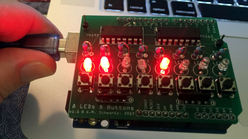
[Allan Schwartz] decided to document his experience using Fritzing to design, fabricate, and test a custom Arduino shield PCB, and his step-by-step documentation makes the workflow very clear. Anyone who is curious or has been looking for an opportunity to get started will find [Allan]’s process useful to follow. The PCB in question has two shift registers, eight LEDs, eight buttons, and fits onto an Arduino; it’s just complex enough to demonstrate useful design features and methods while remaining accessible.
 [Allan] starts with a basic breadboard design, draws a schematic, prototypes the circuit, then designs the PCB and orders it online, followed by assembly and testing. [Allan] had previously taught himself to use Eagle and etched his own PCBs via the toner transfer method, but decided to use Fritzing instead this time around and found it helpful and easy to use.
About a year ago we saw Fritzing put through its paces for PCB design, and at the time found that it didn’t impress much from an engineering perspective. Regardless, as a hobbyist [Allan] found real value in using Fritzing for his project from beginning to end; he documented both the process and his observations in order to help others, and that’s wonderful.


Friends don’t let friends use fritzing…
But why? For many purposes it’s as good as Altium and you don’t have to torrent a few gigs.
At this moment I am loving KiCAD. It is only about 800MB and is happy with my Pentium 4 processor. Fritzing takes 17:29 minutes to even load. I’ll rather teach my friends how to use KiCAD or eagle for permanent solutions, and for prototyping give a couple of breadboards. Maybe it’s just the bad experience I had with Fretting…
No, no, it’s perfectly fine if you don’t want to place components on the back side of your board. It’s perfectly fine if you want no official support for how to make your own components. It’s fine that the top copper is orange and the bottom copper layer is another shade of orange.
jfc, people. You could build this board in the free version of Eagle, and KiCad is free as in speech. This post is not meant to be an endorsement of Fritzing from Hackaday, its editors, or staff.
I would call those colours “yellow” and “orange”, I don’t actually have a problem distinguishing them. I think it’s worse that the symbol for those chips are just boxes corresponding 1:1 with the physical package – the Fritzing “schematic” does not in any way what so ever help you understand how the circuit works, it simply shows you how to build it.
I just did a board which has all components on the back, expect for one through hole, which had to. Link : https://github.com/DeshmukhMalhar/Voltemeter
Fritzing is an interesting project because it does offer some kind of seamless transition from breadboard to printed circuit board. However, schematic and layout are just lacking basic quality assurance features. This is even more problematic as Fritzing is tailored to beginners, who probably don’t know many of the intricacies of PCB manufacture.
At the very least, Fritzing needs a reasonable grid for PCB tracks, with bent corners. The PCB looks absolutely horrible, and looks do tell the part here, as the first version of it wasn’t working. If you mess up such a simple PCB to need a respin, even as a beginner, then your tool is probably really bad. Fritzing has no ERC, no DRC, doesn’t complain about unrouted signals, etc. That’s why on the first revision, an important ground connection (!) was left out. You can’t make this up.
The problem with Fritzing is part of its premise: Breadboards are for quick-and-dirty prototyping, while PCBs are something permament. You just don’t make a thrown-together prototype permanent if you have any pretension of quality.
A reasonable program for beginners would have lots and lots of checklists and pseudo-wizards, taking you step-by-step through the layout, e.g.: route power first; have you taken care of decoupling?; are unconnected pins intentional?; did you route every signal before exporting? Fritzing doesn’t do this. The results can be seen here.
In my opinion, Fritzing’s PCB layout engine is extremely problematic. Beginners would be better off using a digital representation of rub-off symbols and drawing (70’s style) than Fritzing; Fritzing suggests reliability, but doesn’t deliver. Its PCB layout engine is a glorified drawing program with all the wrong design choices in the implementation.
+1
Does anybody here know the story with these Chinese PCB prototype sites? They all seem to use the same form collecting the same input parameters, have roughly the same prices, and have pretty much the same shipping options. Are they all just fronting for some common manufacturing facility, or are they independent but copying each other?
I was impressed with the quality of the one board that I had made.
I do not understand why anybody would bother using fritzing or even writing an article about it when there are such wonderfull open source tools as KiCad.
It’s the learning curve. I’ve been wanting to make a pcb for a few years now to tidy up a prototype but can’t get to grips with kicad. fritzing is basically mspaint.
What Bob says.
If I were using these tools every day, it would be worth the effort to learn their bundles of jargon and tool-specific keybindings. I can see that they are powerful tools. But for a hobbyist (like me), it’s hard to deal with fighting your way to proficiency with a couple of these tools just to decide which one you like the best. You might think your favorite is the best, but, trust me, I’ve read a lot of blog postings and online discussions/arguments about it. It’s enough to know that there is no universal solvent.
And, please, for the love of CAD, could someone with a little bit of a clue about good UI design visit one of these powerful packages. I have not seen one that is simultaneously powerful and approachable.
I’m also only using CAD as a hobby, I’m 46 now and I’ve used about 13+ different schematics/cad packages over the years.
(The first few were under DOS).
I have even bought 3 different CAD packages.
Every package has is quirks and KiCad could certainly use a GUI update for ease of use but it does not tick any really bad boxes.
About the worst I have encountered was a package (EdWin) which did not delete a connection from the netlist if you deleted a connection on the schematic. Try to imagine the result when making a pcb out of that…
KiCad can be a bit confusing and has a learning curve, but the getting started manual for KiCad is pretty good.
When reading/experimenting I had a first schematic and pcb drawn in a single afternoon.
It would have been days without the getting started manual.
KiCad is about the best schamatic/PCB combination I’ve ever used and there is plenty of headroom for more complicated designs.
KiCad 5 has been long due and is rumored to be released before FOSEM 2018 (Februari).
I think it’s easy to underestimate what a hurdle it is to make sense of the gerber file-based workflow when it comes to PCB fabrication. Of course for any real work, or work with any real flexibility, it’s not optional. If you’re serious about electronic design you have to have the patience and effort to learn the tools of the craft; it has value that you can’t get any other way. That being said, people don’t always need to go that way. There can be any number of reasons someone doesn’t want to make that commitment right this moment, and there is absolutely value in a tool that lets you get a board made anyway, and in a way that is familiar to you.
Fritzing is good for people who have learning difficulties like me, stuff I already know is ok.. but a steep learning curve really puts me off attempting a project. Using these sorts of applications is good enough, when good enough is all it has to be.