A few months ago, [Marco] picked up a cheap, cheap, cheap laser engraver from one of the familiar Chinese resellers. It’s a simple affair with aluminum extrusions, a diode laser, and a control board that seems like it was taken from a 3D printer controller designed five years ago. Now, [Marko] is building some upgrades for this engraver and his PCB production skills have gone through the roof.
The laser engraver [Marko] picked up is called the EleksMaker, and lucky for him there are quite a few upgrades available on Thingiverse. He found two 3D printable parts, one that keeps the belt parallel to the aluminum extrusion, and another that provides adjustable x-axis tightness on the belt. With these two mods combined, [Marko] actually has a nice, smooth motion platform that’s more precise and makes better engravings.
These upgrades weren’t all 3D-printable; [Marko] also got his hands on a few Trinamic TMC2130 stepper motor drivers. These stepper drivers are the new hotness in 3D printing and other desktop CNC machines, and looking at the waveform in an oscilloscope, it’s easy to see why. These drivers produce a perfectly smooth waveform via interpreted microstepping, and they’re almost silent in operation. That’s terrible if you want to build a CNC chiptune player, but great if you want smooth engraving on a piece of copper clad board.
This project has come a long way since the last time we took a look at it a few months ago, and the results just keep getting better. [Marko] is making real PCBs with a laser engraver that cost less than $200, and the upgrades he’s already put into it don’t add up to much, either. You can take a look at [Marko]’s progress in the video below.
Thanks [dechemist] for the tip.


Excellent video. It was a great update on the current mods possible on the EleksMaker laser engravers (which are already pretty cool, IMHO)
“interpreted microstepping”, what is that? maybe interpolated?
Yeah, that’s a typo. He said interpolated in the video.
I think it’s like interpretive dance, but on a very small scale.
Where is the thumbs up/+1 when you need it. :D
As demonstrated when Medical Crab saved the Earth through the universal language of dance!
I came close to losing an eye recently. No, it wasn’t with a laser but still.. after that experience looking at these open-frame laser engravers makes me cringe!
I mean you’re supposed to wear those torch welding googles while it’s turned on, no problems there
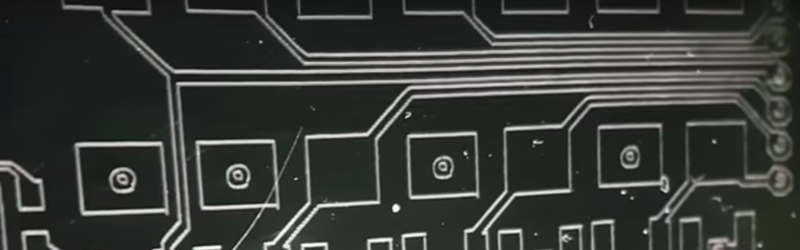
So he’s just etching a resist on the copper, right?
He’s using copper with a layer of spray paint as the resist and using the laser to ablate the paint away, then etching in acid. It’s really nice because you get the tidiness of photosensitive resist without the cost of pre-sensitized boards.
Conductivity, reflectivity. I’ve seen professional machines that do it, but they use high power, very short pulse lasers. It’s so much easier to remove etch resist and let chemicals do the heavy lifting.
forget it with a 300mW laser
Not with that cheap, relatively low-power diode. It would require another beasty laser much more heavy and the whole machinery would be *quite* expensive
He is actually using pre-sensitized boards. He used spray paint in earlier videos.
Ah, I didn’t notice that at first. Spray paint still works ok, just let it dry overnight for max detail holding.
Copper just happens to be an excellent IR reflector, like the best.. so good luck with that.
homing the machine without microswitches….hmmm.
I’ve got a delta printer, and I really want to try that out for bed levelling
Don’t expect miracles. On the X and Y axis the stepper is very directly coupled to the axis, allowing it to move fast. Therefore when it hit an obstruction the forces are much more easily “seen” in the motor current. The Z-axis does not need to move fast and mostly has a very high gear ration between motor and axis. Therefore when the motor hits an obstruction (the bed) it will take longer for it to be detected, simply because of the gear ratio you have more torque, therefore you are able to jam the nozzle deeper into the bed before it will be detected as an obstruction.
Homing X and Y would be OK, as it does not matter when you have an error. Nobody cares if your print is a mm more to the left or the right of your printbed. Absolute positioning is not relevant. But for the Z-axis it is, because you will notice the difference between a nozzle at perfect height above your bed or the nozzle being 0.1mm too high (or too low….. resulting in sounds like SQRRRRRRRRRGGGGGGGGGGGGGG when printing the first layer)
Sounds may differ depending on your machine.
However, this doesn’t mean that the feature is worthless, it’s a great feature, but it must be used for the right things. Saving a limit switch could help reduce cost (no wires, no IO-pin, no switch, no special mechanical requirements). Though I wonder if this detection is automatic or if it is an extra IO-pin/flag signal that can be ignored when not desired. Because sometimes you want the mechanism to continue to move even after hitting an obstruction, though I would not be surprised if this is a setting/configurable. Basically it’s just current sensing and/or EMF measurement. A very useful feature on a stepper motor controller.
I was thinking exactly the same thing for my Delta. I’ve ordered the Panucatt SD2224 drivers for my Azteeg X5 Mini with hopes of removing the force sensitive resistors on my bed for leveling and limit switches for homing. What would be really interesting is being able to detect magnetic ball link failure.
I’ve been doing this with a k40. Works great with some practice. I found that you must let the spray paint dry at least overnight, then you can hold the smallest traces. Otherwise they scrub off. I’m using the cheapest flat black from ace hardware. Also, cut isolation outlines in vector mode, not raster. I’ve been running 3-5 passes with a 0.1mm offset each time to get a wider isolation. In LaserWeb software I use the “Laser Cut Outside” operation. Scale your holes down in the artwork, and the multiple passes will clear the hole center and make a very nice alignment point for your drill. I just etched a FFC connector with .012 traces and spacing. Similar to toner transfer, it’s nice because if the detail doesn’t hold you can clean it off with acetone and try again.
The drivers are way cool. Now, a nearly silent printer? Next on the list of mods.
Would you happen to have an upgraded laser for sale? I am interested in getting possibly 5w to do wood engraving on my custom tables.
I wish I could hear the sound of his finger on the table, but i have a 3d print going on next to me so…..