One of Atmel’s smallest microcontrollers, the ATtiny, is among the most inexpensive and reliable chips around for small applications. It’s also one of the most popular. If you don’t need more than a few inputs or outputs, there’s nothing better. As a show of its ability to thrive under adverse conditions, [Trammell Hudson] was able to shoehorn an ATtiny into an RFID circuit in a way that tests the limits of the chip design.
The RFID circuit only uses two of the ATtiny’s pins and neither of which is the ground or power pin. The ATtiny is equipped with protective diodes on its input pins, and if you apply an AC waveform to the input pins, the chip is able to use the leakage current to power itself. Once that little hurdle is crossed, the ATtiny can do the rest of its job handling the RFID circuitry.
This project takes a deep dive into the internals of the ATtiny. If you’ve ever wondered what was going on inside of everyone’s favorite tiny microcontroller, or if you’re looking for an RFID circuit that keeps parts counts to an absolute minimum, this is the project for you. The ATtiny is more than just a rugged, well-designed chip, though. It’s capable of a lot more than such a small chip should be able to.
Thanks to [adnidor] for the tip!


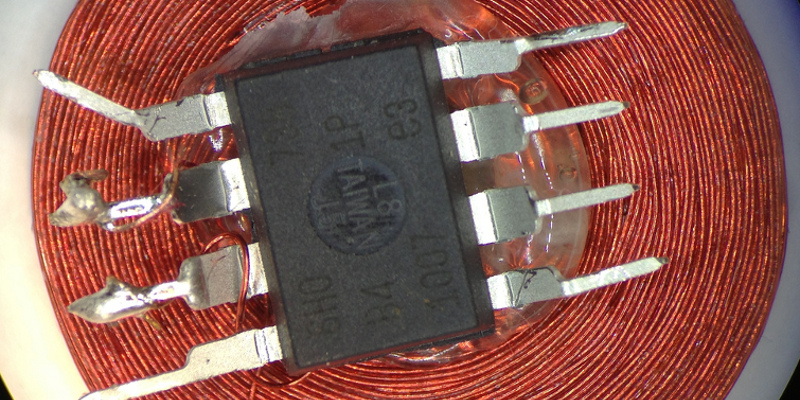
Sort of like this…
https://hackaday.com/2013/01/21/an-attempt-to-replace-multiple-rfid-cards-with-a-single-hacked-together-tag/
Aw heck!
Just enter “ATTINY + RFID” into the HaD Search box…
Almost the 10 year anniversary: http://scanlime.org/2008/09/using-an-avr-as-an-rfid-tag/
When I saw this HaD article, I immediately thought of Micahs project (I think I saw it around 2009 or something).
Or PIC instead ATTiny to find even older post :)
https://hackaday.com/2011/09/26/barebones-pic-rfid-tag/
Yup. I’ve been fond of the PIC12F675 as my go-to 8-pin micro. But the ATTiny is pretty great too.
I even discovered this hack 22 years ago, 1996. That’s a bit older than [Micah]’s take of it with an AVR, despite her great expertise and great ideas on countless projects, she was not the first on this one nor is [t4f] a year earlier (2009) with a PIC 12F683. Who has older proof ? ????
Search for a bulgarian design with a PIC 12C508 for a Microchip contest called design for dollar$.
Lol. I must have discovered this article on HaD a few years back, and then I linked it on reddit a few days ago. And now it has made a full circle. But this hack is so awesome, it really deserves repeated posts.
That’s pretty cool.
I’m surprised the chip can even work like that.
So a small capacitor across VCC and GND for added stability would work in “flaky” situations?
The small capacitor is a decoupling cap and there to remove the AC interference, I believe. This is especially needed when the power supply is an oscillating radio frequency.
Ummm … no? Think of it like putting the big electrolytic capacitor of your standard AC to DC power supply circuit before the bridge rectifier. Not going to work. The point of this article is that the ATtiny recifies the AC from the RFID coil internally. You can’t add stability with an external cap. Sorry.
Did you consider:
The coil is connected to I/O pins that (internally) have diodes to VCC and GND.
Then the cap on the VCC to GND provides the reservoir to hold the charge collected,
Except that the one across VCC and GND is after the AC is rectified by the diodes in the ATTiny.
The one directly across the coil in some earlier examples isn’t… but we aren’t discussing that one.
You are right [Redhatter].
A cap on the GPIOs should be in parallel with the coil and help make it resonate at 125kHz.
But decoupling cap and zener shall be put after the internal rectifier made by the body diodes, and this is possible as this is the Vcc and Gnd pins of the chip!
I have not looked at what the chip is doing but it would be cool if you could use an ESP8266 and read the over wifi.
For “RFID power mode” you’re a few orders of magnitude short on the power budget, wifi is very hungry.
The rectified voltage should be present on the vcc and gnd pins. Perhaps adding a cap there would help in the stability?
I’ve tried various caps between vcc and gnd, and found no difference with or without. The only cap that makes a difference is the one in parallel with the coil. Credit card sized coils work fine without a capacitor, but tiny coils (1-2 cm) work only if inductance is matched with a cap for resonance.
The capacitor across the coil is a little puzzling. The Atiny does not function on AC. The internal clamping diodes are the full bridge rectifier. A capacitor on the output would store the energy and smooths the voltage as a normal AC to DC power supply would.
In this circuit, the voltage across the capacitor is depended on the magnetic field of the card reader. When using a higher powered card reader, the voltage can rise above the Atiny spec and destroy it. I would recommend adding a zener diode across the DC input as well.
My guess on the capacitor on the input is rejecting high-frequency noise.
Resonance, the capacitor across the coil is for Resonance and increase the voltage value. Another one in vcc-gnd would indeed decouple the supply 0.1uF? Maybe less…
The rectification of the ac wave is done through the ESD input diodes (se input circuit of a cmos).