When it comes to finding what direction a radio signal is coming from, the best and cheapest way to accomplish the task is usually a Yagi and getting dizzy. There are other methods, and at Shmoocon this last weekend, [Michael Ossmann] and [Schuyler St. Leger] demonstrated pseudo-doppler direction finding using cheap, off-the-shelf software defined radio hardware.
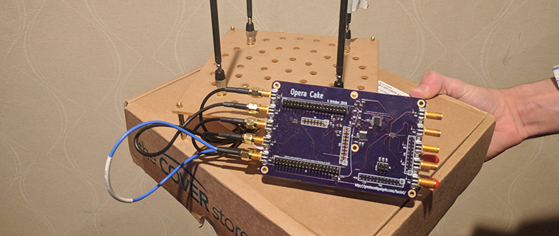
The hardware for this build is, of course, the HackRF, but this pseudo-doppler requires antenna switching. That means length-matched antennas, and switching antennas without interrupts or other CPU delays. This required an add-on board for the HackRF dubbed the Opera Cake. This board is effectively an eight-input antenna switcher using the state configurable timer found in the LPC43xx found on the HackRF.
The key technique for pseudo-doppler is basically switching between an array of antennas mounted in a circle. By switching through these antennas very, very quickly — on the order of hundreds of thousands of times per second — you can measure the Doppler shift of a transmitter.
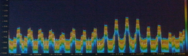 However, teasing out a distinct signal from a bunch of antennas virtually whizzing about isn’t exactly easy. If you look at what the HackRF an Opera Cake receive on a waterfall display, you’ll find a big peak around where you expect, and copies of that signal trailing off, separated by whatever your antenna switching frequency is. This was initially a problem for [Schuyler] and [Ossmann]’s experiments. Spinning the antennas at 20 kHz meant there was only 20 kHz difference in these copies, resulting in a mess that can’t be decoded. The solution was to virtually spin these antennas much faster, resulting in more separation, and a clean signal.
There are significant challenges when it comes to finding the direction of modern radio targets. Internet of Things things sometimes have very short packet duration, modulation interferes with antenna rotation, and packet detection must maintain the phase. That said, is this technique actually able to find the direction of IoT garbage devices? Yes, the demo on stage was simply finding the direction of one of the wireless microphones for the talk. It mostly worked, but the guys have some ideas for the future that would make this technique work a little better. They’re going to try phase demodulation instead of only frequency-based demodulation. They’re also going to try asymmetric antenna arrays and pseudorandom antenna switching. With any luck, this is going to become an easy and cheap way to do pseudo-doppler direction finding, all enabled by a few dollars in hardware and a laser-cut jig to hold a few antennas.


Anyone have a link to more info on this? I’m very interested in more details.
Agreed. There is no info. And why is this “Doppler”? It looks like phase measurements with 4 antennas.
It’s been a while, but from memory:
You can move the antenna, OR switch between them, OR just have a phase delay between elements (not so easy if you change frequency). The effect: when the antenna moves “toward” or “away” from the source, you get a Doppler shift.
Correlating the shifts to the switching of the elements gives you direction.
I concur TheRegnirps. This does seem more like amplitude phase measurements rather than traditional Doppler RDF. With Doppler I thought you had to have a baseline heterodyne RF signal setup locally, then as your virtual-spinning aerials approach the DF target or falls away from it, you notice Doppler shift in the audio tone component. You can mathematically measure the phase bearing angle from the audio tones generated.
I think I would prefer a more expensive symmetrical setup with 4 separate SDRs (on same frequency) and 4 separate Yagi-Udas aimed at the 4 cardinal directions (90° separation each). You would just programmatically poll each SDR for the carrier amplitude strength (from the AGC), and then mathematically compute the amplitude phase angle from one of the two Yagis that are the strongest receivers of the target signal. This vaguely reminds me how Alexa uses it microphone(s) to point LEDs in your (the person speaking) direction when listening for verbal commands. Yes Alexa visually points at you with directional light display when you are speaking! (I love this Echo Dot gadget – best invention ever! Next to the Internet and Railroad.).
However, Doppler RDF is a more efficient and less expensive use of electronic hardware.
If anyone would like more information on audio direction finding techniques, Google everything you can on the ShotSpotter patents. Here at: http://www.shotspotter.com/patents They use similar electronics to gather directional data on gun shots in the field (used in US military in SW Asia to locate snipers). By using several ShotSpotters in a tandem configuration, you could get an exact location within milliseconds of occurrence. Now just evolve that to RF signals… However, the operational Calculus involved is a real math nightmare to Calc-Lite people like myself! 8-)
Here’s an example of what I was talking about as to the invention and the Calc involved: http://www.google.com/patents/US8995227
It’s pseudo-doppler. You feed the antenna switch into an FM (or PM) receiver, and the result is a tone modulation – low pass filter it, you get a sine wave, measure that phase of that, after calibration, against the switching signal, and you get the bearing. Lots of folks use this with just ordinary ham FM radios, an antenna switch box, and an audio processing and display box.
Est-il possible d’adapter ce système rdf pour les gammes de fréquences HF?
Same here, I’d like to know how to gang these units to get full positional information for mobile phones transiting through an area, for a physical security application.
All this work for something do-able with using what doppler shift actually does. Doppler shift can be explain very simply. A train is coming down the tracks. It blows it’s horn, as the train is coming at you the sound of the horn rises. The sound is being pushed forward just slightly. As the train passes the sound shifts in frequency lower and get lower as the train go’s by. This is doppler shift. If you listen to the audio and detect when that shift occurs, you will know the direction of the signal. The source of the signal does not change in RDF. But the rotating antennas do. Which is why it works. Rotating at 20KH is very high and leads to all kinds of problems. The antenna switching only has to be at the speed of sound in the circle of antennas used. The larger the diameter the faster the rotation must be. Back when I played with this stuff, that frequency was around 250 HZ, required only 1 radio and listened to the audio shift. I had lot’s of fun on the bunny hunts.
Indeed.
The traditional doppler RDF circuit is a CD4066 quad switch and a 555. You can detect the timer’s frequency and use the phase between that and the 555’s output to figure out the relative direction. Or use your earballs and move the antenna to find the null.
I saw something similar demonstrated about 15 years ago at a Science Open Day at the University of the Witwatersrand, Johannesburg. (I think it was organised by the Amateur Radio League here). The guy used a PIC CPU, and switched 4 antennae in a similar way in sequence 400 times per second. 8 LEDs showed the closest detected direction of the transmitter. Seemed like magic to me at the time.
There were plans for this system in older editions of the ARRL handbook. Some versions used 1N4007 diodes as RF switches, as I recall. I’ve thought about re-doing this using a cheap Baofeng HT as the receiver. You could find sources on FRS, GMRS, MURS, 2m, 70cm, and, of course, your local taxis.
Here are plans for this type of system from 1999:
http://www.n5dux.com/ham/files/pdf/Doppler%20Radio%20Direction%20Finder.pdf
This is complex stuff.
It seems like MIMO setups are becoming popular in some types of radios, like WiFi and 4G, and you can do a *lot* with these things, probably much more than with this antenna switching device. In any case it’s very complex shit and matching that with SDR makes it even more complex but work is being done in the big companies and PhDs are being written on it. Hopefully some of it will be public and reusable. With a 4-antenna MIMO radio you can not only find the direction of a received signal but you can actually do beamforming, i.e. blast a signal in a specific direction in 2 dimensions
In any case… “With any luck, this is going to become an easy and cheap way to do pseudo-doppler direction finding, all enabled by a few dollars in hardware”… hmm doesn’t not sound like it. For this technique to be perfected and then the Opera Cake setup + all of HackRF to become a few-dollars in hardware that’s definitely not happening “with any luck”
True beamforming (not just random mangling like Cisco’s take on 802.11ac can do) needs phase shifters on every antenna…either analog using ferrite delay elements or digital using either fast transistors or PIN diodes and a set of discreet phase delay lines (printed on a PCB for higher frequencies or actual lengths of coax cable)…cost of all of these starts to add up quickly once you need to build an antenna array :(
In general, beamforming uses different phase *and amplitude* for each antenna.
But, if you are using SDR, you do that in software, either for receive or transmit. But it does require that all the SDR paths be coherent – use the same oscillator.
That antenna switcher is pretty sweet, can be controlled via I2C and can automatically switch when the hackRF changes frequency bands.
But now I wonder, is there a simple 2 input antenna switcher like that available from the usual Chinese sources for ‘plain’ SDR? Anybody know and got a name of it?
Solid state RF switch. Not seen that much ready made modules from asian sources.
One could lurk on eBay for manufacturer devkits.
Sklyworks has nice easy to use chips. Same with M/A-Com and Analog Devices(Hittite). Single pin or two pins command between switch ports.
Command that with a GPIO pin off RTL2832u or some I2C IOExpander.
Solid state RF switches are available from large distributors, up to around 6GHz they’re even reasonably priced. They even come in more then just 2 I/Os ;-)
Only problem I found with them is as they’re all designed for consumer electronics, most top out at +20dBm of power input at most and they loose a couple of dB passing through, so you can’t really chain them too much to form complex switching networks, as the signal loss would become unacceptable…
The nicer ones that can take more power or have less input loss are probably made of unicorn farts or something and thus are 1) unobtainium 2) stupidly expensive
Mini Circuits dot com….
BanMENOW – Yes here is a switch that would probably do the trick from them. It’s $169.95 from Mini-Circuits.
https://www.minicircuits.com/images/case_style/QV2425.png
ZSWA4-63DR+
SOLID STATE 6GHZ SP4T SMA
Connector Type: SMA
I think you’ve been away from HaD too long. We are an eclectic bunch and many have some really leading-edge ideas here that rival DARPA stuff. It doesn’t matter if we resurrect old stuff, it’s still interesting to us. We might be able to do it better! And Brian is one of our forum leaders and he is awesome… [I’m not being sarcastic Brian. I really feel that way.]
Worked on an analog HF version back when I was in Army in late 70’s. Original concept was developed in the early 1900’s. Nice job making a modern version out of the old analog/mechanical systems. REF: Bellini–Tosi direction finder
Yeah it seems like it would be a lot easier with a proper 4-MIMO SDR e.g. http://www.analog.com/en/design-center/evaluation-hardware-and-software/evaluation-boards-kits/eval-ad-fmcomms5-ebz.html
Yes for $1125 each, I’m sure it could be.
Well you can get two AD9361 chips for ~$200 each and design and build your own board. But you may need several extra chips to get the design right.
Switching between antennas to create a “virtual” spinning antenna?
Last time I saw a spinning antenna it was a navigation aid called TACAN.
https://en.wikipedia.org/wiki/Tactical_air_navigation_system
Haven’t you ever seen a mechanically scanned radar antenna? :P
Balint Seeber already did this like back in 2012 using a USRP. Pseudo Doppler direction finding has been used for a long, long time. You used to be able to buy kits from Rasmey Electronics, but they got out of the kit business a few years ago. As other have said, there are still plans online based on switched filters and simple switching diodes for the antenna switches. ARRL May 1999 comes to mind. This is why I rarely read HaD anymore, always a day late and a dollar short…. I find more information via my own web searches and stumble upon all the stuff HaD steals and then writes up…
whats is the price of operacake
how can i get it?
Vaporware!
My design is coming along – https://hackaday.io/project/163957-yet-another-doppler-direction-finder-w-teensy-dsp
Hi,
has anyone found a source for a fully assembled and tested HackRF Opera Cake?
R
Reading the comments, I think that a lot of readers may profit from the background information on my website.
I’ve been experimenting with pseudo dopplers and amplitude RDF’s for the last 10 years or so.
http://members.chello.nl/~w.hofman/pa8w/index.htm
You haven’t publised much
details. I looked for amplitude based info and didn’t see it. Are you familiar with the MUSIC algorithm?
I haven’t published much, but what I published works.
http://members.chello.nl/~w.hofman/pa8w/AmplitudeRDF.htm
http://members.chello.nl/~w.hofman/pa8w/AmplitudeArray.htm
How to build a 23cm Amplitude array
I know the MUSIC principle but I don’t use it in my approach.
A good RDF starts with thorough understanding of antenna behavior in each others proximity plus awareness of the drawbacks of hard switching (if antenna switching is involved in the system).
If the front end is neglected there’s no algorithm that can save the day.
Like building a car with egg shaped wheels and have a computer sort out how to continuously adjust the suspension to compensate for that…
I have a project that requires direction finding of a 2.4ghz transmitter, but unfortunately kerberos SDR doesn’t reach 2.4ghz, I already have HackRf one and I want to do this, so my question is can I do this and if I can how can I do it ?
thanks in advance
Yeah, right… http://www.picodopp.net or http://www.picodoppler.com
Then https://home.hiwaay.net/~pelican2/PicoDopp/PICO_MORE.html
then try https://home.hiwaay.net/~pelican2/PicoDopp/ABOUT_DOPP.html
and https://home.hiwaay.net/~pelican2/PicoDopp/MORE_PULSES.html
DE WB6EYV
PA8W is an accomplished Doppler maker, folks should listen to him… so am I, WB6EYV… maker of PicoDopp DF, look it up…. and like him I have background info on my own Doppler DF website also… The caliber of the technical conversation here is quite low, that’s why he suggested a read of background material on his website… and I make the same suggestion about mine also…