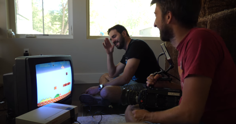
Analog TV is dead, but that doesn’t make it any less awesome. [Gavin and Dan], aka The Slow Mo Guys recently posted a video about television screens. Since they have some incredible high-speed cameras at their disposal, we get to see the screens being drawn, both on CRT and more modern LCD televisions.
 Now we all know that CRTs draw one pixel at a time, drawing from left to right, top to bottom. You can capture this with a regular still camera at a high shutter speed. The light from a TV screen comes from a phosphor coating painted on the inside of the glass screen. Phosphor glows for some time after it is excited, but how long exactly? [Gavin and Dan’s] high framerate camera let them observe the phosphor staying illuminated for only about 6 lines before it started to fade away. You can see this effect at a relatively mundane 2500 FPS.
Cranking things up to 380,117 FPS, the highest speed ever recorded by the duo, we see even more amazing results. Even at this speed, quite a few “pixels” are drawn each frame. [Gavin] illustrates that by showing how Super Mario’s mustache is drawn in less than one frame of slow-mo footage. You would have to go several times faster to actually freeze the electron beam. We think it’s amazing that such high-speed analog electronics were invented and perfected decades ago.
Switching from CRT to LCD, the guys show us how the entire screen stays lit, while refresh runs top to bottom. Experimenting on an iPhone 7+ showed that the screen refresh is always from the top of the screen down, toward the home button. If you change the phone to landscape orientation, it will appear to be refreshing from left to right. All pretty interesting stuff, so check out the video. If you’d like to know more about TV technology, read up on the Sony Trinitron story, or learn about the signals used in displaying video.
Thanks for the tip [Quirin]!


Minor nit: voltage doesn’t pass through anything… current does.
They couldn’t. I mean, they’re scientists right? The wear white coats!
They*
“one pixel at a time”
https://www.youtube.com/watch?v=dX649lnKAU0
Yeah my bad. I even used pixels in quotes later on in the article. To the tv it is a continuous analog voltage.
Interesting an LCD would have a raster.
ALL display types are a raster. Unless you talk about older displays like vector scopes used in CRT oscilloscopes, some old arcade games and computers.
Rather than a left to right line by line drawing like a CRT, a vector scope can move its point of light to any random location on the screen, so if you draw a circle only the circle pastern gets drawn, not a line by line representation of a circle.
https://www.youtube.com/watch?v=ZaTuFB5QXHo
The closest modern equivalent we have to a vector scope would be a laser light show like in a night club, Or technically the newer laser projector TVs could be used as a vector scope, but in principle they are scanned in a raster just like an old school CRT.
The display itself doesn’t, but the update of the display is.
I think you are confusing raster scan with raster graphics
https://en.wikipedia.org/wiki/Raster_graphics
https://en.wikipedia.org/wiki/Raster_scan
But in the end as shown in the video even today’s modern LCDs are raster scanned. Just at a much faster rate than NTSC TVs of old.
The only possible way to not raster scan an LCD would be some kind of latching buffer in each pixel. The pixel data would still be raster scanned into the buffer, then all the buffers could be latched at once to update the entire screen at that moment. This would make LCD panels incredibly more complex and expensive than they are today. When we can just raster scan update them faster than the eye can see it.
Even then there is still the fact that digial connections used today like HDMI are fundamentally serial connections anyways, even if multiple channels are used in the HDMI cable. There is no possible way to get a whole screens worth of data to the display at any single moment in time, so again raster scanning is used as the pixel data is clocked in over the serial connection
There is also the fact that even today’s LCDs are still slower to update than a CRT would be. Sure we never had 120/240Hz NTSC TVs, but the CRT technology is completely capable of it. There just isn’t enough bandwidth in an analog NTSC signal to perform updates that fast.
Analogue TV is not dead: amateur television (a branch of amateur radio) still features both analogue and digital systems, the analogue even including some who use the ole 1920s Baird system of spinning discs. It probably always will, for the same reason that some amateurs use glowing tubes while others use SDR (or some musicians play harpsichords while others play Moogs).
For all intents and purposes it is pretty dead. I myself have never actually seen an ATV station on air. I have an Icom IC-R3 which was capable of picking up Analog NTSC TV, and ATV anywhere from 30Mhz up to 2.4Ghz, and displaying it on it’s tiny LCD screen. Alas there is nothing to be seen on air anymore these days.
The only hopes I have today of seeing anything on it’s screen today is firing up an old UHF modulator I have or some old analog 900Mhz or 2.4Ghz cameras.
I’ve heard that phosphor coatings can be a real pain, but aren’t they painted on the screen? ;-)
For tektronix CRTs they would suspend the phosphor in water and pour that into the CRT. The phosphor then settles out in a pretty even layer. Im not sure how they did it with television CRTs, probably similar but with a mask.
I would imagine on a shadow mask CRT it is much more complicated. Somehow the different color phosphors have to be deposited in the correct place. Unless the phosphor is all white and there is a colored filter, possibly silkscreened onto the glass face before the phosphor is layered on top.
Depends on the screen. My father used to work at the level of repairing the tube itself, would even get them filled afterwards at the local AirGas store using adapters that he made from plumbing parts. Some screen it’s actually a layer of material over the surface of the screen that you can heat with a heat gun at around 400-500F to loosen up enough to slide right off. Those were really cool, the current passed through the metallic film allowed for intensity (brightness) control and IIRC frequency controlled contrast. Those were the ones where you had to tune the horizontal and vertical alignment every now and them to eliminate ghosting in still images. More often than not they were inside the tube itself and not removable though a little chemistry goes a long way to restoring them. For example the easier ones to fix we would wash the tube with distilled water then pour in powdered nickle, apply a small charge, rinse again with distilled water then fill with appropriate medium.
When I say filled that definition changes. Some tubes are gas filled, some a vacuum “filled” and others were beyond our repair as they contained mercury. None of them were profitable to repair, mostly did it just to learn how the various CRT technologies worked.
They use a source that doesn’t do interlacing it seems then? So that is NOT showing how old TV works at all.
Old nintendos don’t interlace, they only ever display about 240 lines of the even or odd, i dont remember field. That’s why they appear to have black lines between each of the scan lines even when looking at it with the naked eye. If it did both even and odd frames those black lines would get filled in.
Even if it was interlacing, in the time period they showed on most of the clips you would have never seen the other field filled in, since it has to draw all of the even field, then go back to the top of the frame and draw the odd field.
Old nintendos can trick old TVs into doing progressive because at the top of the field there is a signal if the next field being drawn is even or odd, The nintendo just never changes this signal, so you get a progressive scan, at half the resolution a TV can display.
This is also why emulators have to either make the pixels double height, or insert fake black scan lines. If you displayed the resolution the nintendo outputs using square pixels you would end up with a squashed 240×480 or so image.
If you purport to show hold old TV’s work you HAVE to cover interlacing though.
And even if you don’t see the beam you’d see a black line.
And the whole idea of interlacing AFAIK is that the phosphor had some light left when the next frame came around so it blended somewhat, which is why old interlaced material in video on modern displays needs deinterlacing to not look noticeably off I’m told.
That reason for interlacing would not be true. Old CRT PC displays were all progressively scanned. except for the very early ones that just used old TVs. Old PC CRTs had over 100mhz of bandwidth available on the VGA cable, where as NTSC is allotted 6mhz. The reason for interlacing in NTSC TVs is because there is not enough bandwidth in the 6mhz signal to send an entire frame progressively.
If you wanted to send a progressive scan image though the 6mhz of bandwidth that NTSC was allotted, then the only way would be to reduce the resolution, or half the frame rate to 15fps.