[miroslavus] hasn’t had much luck with rotary encoders. The parts he has tested from the usual sources have all been problematic either mechanically or electrically, resulting in poor performance in his projects. Even attempts to deal with the deficiencies in software didn’t help, so he did what any red-blooded hacker would do — he built his own rotary encoder from microswitches and 3D-printed parts.
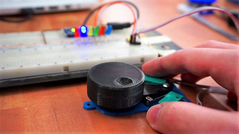
[miroslavus]’s “encoder” isn’t a quadrature encoder in the classic sense. It has two switches and only one of them fires when it turns a given direction, one for clockwise and one for counterclockwise. The knob has a ratchet wheel on the underside that engages with a small trip lever, and carefully located microswitches are actuated repeatedly as the ratchet wheel moves the trip lever. The action is smooth but satisfyingly clicky. Personally, we’d forsake the 3D-printed baseplate in favor of a custom PCB with debouncing circuitry, and perhaps relocate the switches so they’re under the knob for a more compact form factor. That and the addition of another switch on the shaft’s axis to register knob pushes, and you’ve got a perfectly respectable input device for navigating menus.
We think this is great, but perhaps your project really needs a legitimate rotary encoder. In that case, you’ll want to catch up on basics like Gray codes.


> nor is any information about the speed or direction of the shaft’s rotation captured
Hmm, speed can be captured from clicks time and direction is captured directly, you have either left or right clicks. Absolute position is not captured, but it’s not always needed.
Fixed.
Nice out of the box thinking, but the “solution” relying on mechanical assembly seems to outweight the advantages, I guess the non original solution would have been just to find the proper encoder for his need…
It seems like he did find it.
Apparently this guy has never heard of debounce and his code must be pretty awful. I have used these encoders and they work fine.
+1
Actually I used a lot of different rotary encoders either bought or salvaged using this library: https://github.com/0xPIT/encoder/tree/arduino and never had any problems.
And if you don’t want to use a library for some reason, I made some simple sketch-based code for the ATMEGA328P which some people may find useful –
http://www.instructables.com/id/Improved-Arduino-Rotary-Encoder-Reading
Got some that where pure garbage, other that were fine. So YMMV.
I’ll second this one. There are encoders out there that are absolute junk. When you try to smooth out the bounces, the time constant becomes so slow that you miss intentional steps when it’s turned quickly.
Don’t scrimp on encoders.
And this project is cool. I love the click of a microswitch.
Don’t get me wrong. I like the way miroslavus solved his problem. But I think had he used the correct software for his specific hardware there would not have been a problem at all. What I discovered with encoders is:
1. some encoders generate 1, 2 or even 4 impulses per mechanical click
2. most librarys/codes function better for a specific order of input pins. Other words: it matters if you connect pin a of encoder to pin 1 on your micro and pin b of the encoder to pin 2 on the micro or the other way round.
Point 1. is taken into account in most (better) libraries and you can provide the number of impulses per tick e.g. in the constructor of the encoder object.
2. is a simple try and error. If the order is wrong the value “flickers” right in the middle of the mechanical tick.
Apart from that I did not experience any issue with encoders, regardless how cheap they are.
“Don’t scrimp on encoders.”
Grayhill used to make a fantastic line of encoders, # 62P22. Alas they make them no longer and I think the world is poorer place as a result. These were optical encoders with a (mechanical) pushbutton and were pretty cheap. Courtesy of the optical aspect, I never even needed to debounce the rotation.
I use the gray hill 62s encoders and they are probably pretty close to the same, you can get them new surplus here: http://www.surplusgizmos.com/Grayhill-16-Position-Optical-Encoder-62SY22096-62S22-H9-020C_p_2329.html
+3
While I applaud his work to figure out a solution and I know one manufacture’s detent is not necessarily another’s, I have had pretty good luck getting encoders to work in place of +/- buttons in multiple machines without much fuss beyond a diode or two. Dunno if he just has bunk parts or bad luck :(
Do people really have that much trouble using a standard rotary encoder?
If you’re missing steps or getting extra steps it generally means you’re either missing pulses or your code is broken. For the latter, there is lots of sample code out there and ready to use libraries. For the former, missing pulses is most easily fixed using interrupt pins, but if that’s not an option you just need to be sure not to tie up the microcontroller too long in between polling.
As long as you’re not neglecting nor abusing it, it should work without any particular magic. I use a slightly modified method of reading rotary encoders that can have relatively long lapses between polling the encoder and still stays rock solid. If people are having that much trouble I’ll add it to my todo list to write up a tutorial on how it works.
> If you’re missing steps or getting extra steps it generally means you’re either missing pulses or your code is broken.
A quick correction to myself: Depending on the type of rotary encoder you can also have bounce issues. That’s a standard issue to fix, and would occur with microswitches as well.
While it’s a great hack, I think it could have resolved by refining code. I’ve had similar problems with an encoder for a project, and I discovered two things.
The first is that there are many types of encoder out there. I thought it was straight forward: One change on one of the two channels = one clic. In fact this is often a change on each channel one clic: one change on channel A (or B), followed by one change on channel B (or A, respectively). And For some, it’s even a complete cycle: change on both channels, followed by another one, so each clic has exactly the same position for both channels!
The other thing I discovered is that if values from 1 to 5 milliseconds are reliable for debouncing buttons, encoders need to be faster than that. It works well with 1ms when you turn them gently, but for reliable change detection, I found that 200us are a good start. On the project I use them, I can turn the encoder by hand without having step loss.
I’ve wrote a library for Arduino, that take care of this two points, feel free to use it if needed! https://github.com/troisiemetype/Encoder
I do agree that the ones typically used on the ‘development’ modules he is buying are a bit on the low quality side.
Just buy your parts separately from farnell/digikey/etc and there are tons of encoders to choose from in terms of quality and the number of steps per resolution. Debouncing is always necessary hower. Doing it in code is the most economic but you can use schmitt-triggers is you want it to be bulletproof.
Also, Bourns makes some really high end optical encoders, these are a joy to work with, but cost you +$30 a piece. Just dont forget to supply the right voltage, most don’t work on 3.3V as I found out the hard way.
Just a small addition:
I do like what he has done. I would go for the off the shelf part but his design does have it’s uses.
If for example you want a very specific weight or feel to the knob, or you want a non-standard number
of clicks per resolution, this could be your ticket.
I would have designed screw holes for the switches, just so you can mount them in the optimal position without fiddling wit the glue.
Add an end stop switch and you have a custom fallout 4 pipboy style selector switch ;-)
It is one thing to dedicate almost all of the resources of the MCU to monitor the switches and another to do multiple tasks while monitoring the rotary encoder at the same time.
Clicky detents and the clicky sound of microswitches aren’t what make a reliable rotary encoder. Any encoder using mechanical contacts are bad in my opinion. Go optical or hall-effect — and has anyone heard the term ‘quadrature’ ?? It won’t even be that expensive to make them (3d print them or whatever) just look at Homofaciens youtube videos on encoders.
Some people like mechanical, and believe it or not it’s plenty wear-resistant for its purpose. You need optical or Hall-effect reliability for something like an ignition sensor that pulses at 5000 rpm for hundreds of thousands of miles, and even then there have been quite reliable mechanical alternatives. You’d be surprised how long a set of points will last.
You actually should not debounce a quadrature encoder, but you might want to smooth the output value. Bounce will just oscillate you between two adjacent values; it won’t cause you to miss steps, unless to rate of turn is so high that the bounce goes well into the next quad, and then you’re screwed using any technique. I’ve seen some bad quadrature decodes, including a car stereo that turned the volume down if you turned it up too fast.
THIS!
No denouncing necessary, but small capacitors help a lot!
And when it comes to HID’s, using a microcontroller for real time tasks AND an interface (which is a real time task as well), everything comes and goes with the right tool (in the controller!).
Many controllers have a timer with quadrature encoder inputs. Hardware counting your steps, you just read out whenever it is needed.
THIS is the best way to get a reliable wheel!
Polling creates troubles in some cases, and to overcome those, the polling rate has to be increased. So you have all the time this high priority task blocking the rest of your application, for just seldom cases where it would be needed.
Furthermore, crap encoders can keep you busy enough, and having two possible problems, makes it hard to find the cause.
that requires that you do proper decoding, and not the horrible hack of using one channel as direction and the other as clock
Yep.
Theses aren’t encoders, they are properly called RPG (Rotary Pulse Generators).
It’s a State Machine. When one signal transitions, that’s a hit. Further transistions should be ignored until there is a transition on the *other* signal. That way you avoid the debounce and double hits.
The reason why his encoder on the 3D-printer does not move one line with one click is because Marlin is set up incorrectly. These encoders only make ONE “pulse” per click, but you can set up a divider in Marlin, which is what you are seeing there. It’s not the fault of the encoder. What OP is seeing is bad software – it has nothing to do with the encoder switch itself. Sigh …
100%….(cuz marlin jus sucks in general, but has extremely poor encoder handling)… although some of these encoders are pretty crummy. BUT , there are many many options outside the typical dime a dozen encoders littering Ebay and Amazon.
this project is ingenious, but i fear the plastic will wear down where it contacts the wheel. another way would be to print a gray code inside the wheel and mount each microswitch on top of each other.
All you need: proper interrupts and debounce capacitors. I’ve been here done that, and this is the solution.
Only needed parts are 2x shitty capacitor and proper code. How hard can it be? I guess it could be “print your own hardware solution” hard. Ah well, he got it working the way he needed.
I talked about a Timer for this’ll job – a step back – interrupts would be sufficient I guess.
Time for an article about this topic here on Hackaday!
The pros and cons of the different implementations…
@X above linked to an Arduino library that is derived from some C code by Peter Danegger that uses my favorite algorithm for decoders. So there’s that article! :)
Seriously, though, it would be a neat topic. There’s a lot to say, as you can see from the comments here. Between mechanical (debounce) and firmware (bad decoding, not making the polling intervals, etc) there are all sorts of pitfalls.
My car’s console system, for instance, has trouble reading the encoder when it advances to the next step in a multi-step menu. I think it’s because it is polling and encoder and has to suddenly do so much extra processing that it can’t keep up with the turning knob. Or it could be something worse. :)
Rotary encoders have been around for a long time. They seem to be a pretty mature technology. That being said, your design is neat. I would look into getting rid of the ball bearing, make a tighter fit and use grease. The thing is not going to ever have a big load on it or go hundreds of RPM. Next, I would look at getting rid of the thing in the center that clicks the micro switches and have the teeth directly engage the switches. It would also be nice if the base plate had some kind of retainer for the switches. A simple channel for the side of the switch to fit into to hold it in the proper position, and have mounting holes. The proper position would be more critical with the switches touching the teeth directly. And last, print the knob and the gear as one piece. Get rid of having to glue things together. That would take the number of parts down and make is a much simpler beast to assemble. It is a neat project.
I also found shaft encoders being extremely useful with microcontrollers, so rolled out my own component for Cypress PSoC type micros
https://community.cypress.com/thread/30654
Out of those found on eBay, about 50% are jittery with back-and-force jumps, but obtained from Digikey are of good quality. eBay-sourced are inconsistent, bought from different vendors they may have opposite direction of rotation and steps per revolution, while looking pretty much same. One batch produced unusual 15 steps / 30 detents per revolution.
i think i would have gone with a couple hall latches and some press fit neodymium magnets. probibly a fixed magnet in the base to give you a nice detente.
why not just take the sensor and light from an old mouse, and count pulses to determine movement?
this is a fantastic solution to put rotary inputs on devices that can only read push button input. for example those dirt cheap joystick/game controller boards on ebay.
well done sir