To measure how fast something spins, most of us will reach for a tachometer without thinking much about how it works. Tachometers are often found in cars to measure engine RPM, but handheld units can be used for measuring the speed of rotation for other things as well. While some have mechanical shafts that must make physical contact with whatever you’re trying to measure, [electronoobs] has created a contactless tachometer that uses infrared light to take RPM measurements instead.
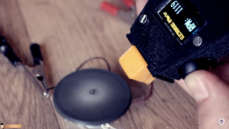
The tool uses an infrared emitter/detector pair along with an op amp to sense revolution speed. The signal from the IR detector is passed through an op amp in order to improve the quality of the signal and then that is fed into an Arduino. The device also features an OLED screen and a fine-tuning potentiometer all within its own self-contained, 3D-printed case and is powered by a 9 V battery, and can measure up to 10,000 RPM.
The only downside to this design is that a piece of white tape needs to be applied to the subject in order to get the IR detector to work properly, but this is an acceptable tradeoff for not having to make physical contact with a high-speed rotating shaft. All of the schematics and G code are available on the project site too if you want to build your own, and if you’re curious as to what other tools Arduinos have been used in be sure to check out the Arduino-based precision jig.


I mean, this is a cool build and all, but the principle of operation here is effectively the standard for handheld tachs. The 3D printed case even has the general shape/design of common commercial models.
Nothing wrong with that, but seems like a lot of this post was dedicated to making the method seem novel.
“The only downside to this design is that a piece of white tape needs to be applied to the subject in order to get the IR detector to work properly”
Seriously Brian? What did you expect. Adding a piece of reflective tape isn’t a downside, it’s the huge improvement compared to a real mechanical linkage. This is pretty normal for the past 30 tears (most likely even longer). Sure other ways of measuring could be using audio and based on the sounds visualized in a spectrum representation the user could determine the base frequency do some calculations and consider that the speed of the shaft… but that is way more of a hassle and not always a guarantee for success.
We could argue about the way it was put together… blablabla… could be easier…. why arduino… a 555 and a simple coil meter could do the trick… but in the end this project works. It does what it needs to do and therefor is considered a success.
Sure you can also buy such a device for about $11 on aliexpress, but where’s the fun in that?
A simple improvement: since there’s multiple unused op-amps in the chip, use one to buffer the signal from the phototransistor and add a lowpass (RC) filter to generate the reference level for the last amplifier.
The lowpass filter measures the signal average, it’s DC-offset, so the circuit becomes self-calibrating to the light level and you don’t have to hunt for it with the potentiometer.
Can that OPAMP be removed? It’s used as comparator, and ATMega328 has internal comparators that can be used for that purpose. With some code fiddling (finding average, using PWM to set reference voltage) it probably could be configured to auto-adjust for different light conditons, eliminating potentiometer.
The analog comparator compares the voltages between AIN0 and AIN1, so you don’t need to do any software tricks. Just filter the signal from the phototransistor with a low-pass RC network, and compare the low-passed result with the raw signal on the other pin. The interrupt will trigger (depending on your settings) whenever the signal remains above or below the average for four clock cycles.
Yup, even better solution.
In this case. However, the analog input may already be in use – for example in an Atmega168/328 the AIN0 pin is shared with a PWM output. In that case, it’s better to have a simple dual op-amp like an LM258 / 358 or a TLC272, or similiar for a buffer amp and a comparator.
Reason being that the phototransistor/resistor pair won’t be able to drive much current and so the cutoff frequency of the RC filter will vary with the light level. Therefore your reference voltage level may hunt around and cause glitches especially when the signal is weak – whereas the op-amp buffer will keep things nice and steady, and the external comparator will allow you to connect to any of the Atmega pins which support pin change interrupts, or the PCINT pins which allow you to use the 16-bit hardware timer capture function which frees your code from the task of measuring the pulse width.
just might have to build that, lost my other one in the airport baggage
Just can’t help it. Need some feature creep. Switchable inputs, a better display for O-scope functionality, another input channel or 2. How hard could it be?
what G code is used in this project? The only code provided are the Arduino sketches but he does provide the STL 3d files if you wish to print it your self.
look words matter and doubly more so in an article trying to teach something to people who might not fully understand the concepts.
PS, whiteout or white paint markers work just as well as tape.
Buried under a few pages of ads:
http://www.electronoobs.com/images/Arduino/tut_15/Electronoobs_RPM_meter_STL_files.zip
or you could buy one for $8.34
https://www.aliexpress.com/item/1set-Digital-Laser-Tachometer-RPM-Meter-Non-Contact-Motor-Speed-Gauge-Revolution-Spin-Free-Shipping/32802408754.html
Yeah, ’cause typing in your cc number is way more fun than building stuff.
Not.
OK, bad design. NEVER leave any unused section of an Op Amp unconnected. Floating inputs will change according to surface charge and nearby static discharge, capacitively couple to outputs. The circuitry may lock up or go into HF oscillation, causing increased power draw and disrupting the sections being used.
Do NOT just ground both inputs. Connect the + input to the output, connect the – input to some voltage between the supply voltage and ground. A simple resistive divider will work fine. All unused sections can use the same voltage source, but put a small bypass capacitor from it to ground.
How many times have you used Op Amps, and gotten frustrated chasing phantom problems? Or the circuit works on a breadboard, but not in the final circuit?
I have seen commercial designs that have improperly terminated unused Op Amp sections. Someone was not doing their job.
https://www.maximintegrated.com/en/app-notes/index.mvp/id/1957
https://www.electronicproducts.com/Analog_Mixed_Signal_ICs/Amplifiers/Properly_terminating_an_unused_op_amp.aspx
Very good, but you got the wrong input. Connect the – input to the output. Connecting the + input will create positive feedback and drive the output to saturation.
Gah! Where’s that edit button? Edit, edit!
You are absolutely correct. Inverting input to output, noninverting input to a voltage divider. Or ground, if and ONLY if there is a positive and negative supply.
Brings back fond memories… About 35 years ago I designed and built ten tachometers for measuring the speed of air-powered dental drills. IIRC the chip I used was a Nat Semi 74C926 – not a micro of course, just a 4-digit counter with built-in 7-segment drivers. Had to handle the timing and gating externally with glue logic. The IR emitter-detector pair was packaged in a black cube about a quarter inch on a side, and I made a reflective bit with black magic marker on one half and Wite-Out on the other, covered with clear heat-shrink. It worked to at least 180 kRPM – I seem to remember pushing a drill to 300kRPM one time, but memory is a bit hazy. I actually learned to make silk screens for that project – made frames, stretched and stapled fabric, applied emulsion, exposed the screens through my hand-taped / dry transfer artworks using a tanning lamp, screened the PCB’s and the cases, etched the PCB’s, and scrubbed off the screening ink. (Along the way I discovered to my chagrin that Scotch Magic Tape blocks UV pretty well).
The tachs were also supposed to measure exposure by counting the X-ray impulses from dental X-rays, but I never got that part working because I didn’t realize until much later that I needed special fluorescing paint on the solar cells.
Apologies for the long winded reminiscence…
I think the write up has the explanation of the photo transistor action reversed. When light strikes the transistor, it conducts.
I once made something like this by attaching an LED to a cellphone mic input (LEDs also work in reverse as inefficient photocells), shining a flashlight on the spinning object and running a free oscilloscope app on the phone (OsciPrime, I think). But this is a much less clunky setup.