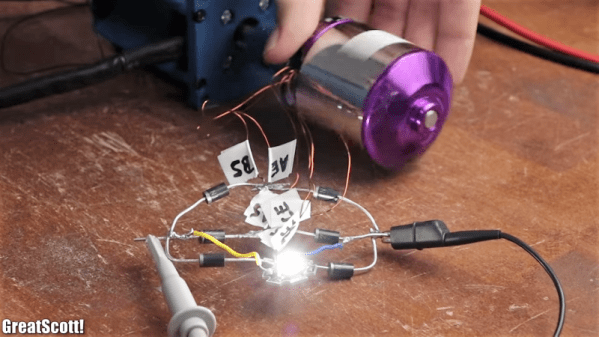
Rewound And Rewired BLDC Makes A Half-Decent Generator

What’s the best way to turn a high-powered brushless DC motor optimized for hobby use into a decent low-RPM generator? Do you take a purely mechanical approach and slap a gearbox on the shaft? Or do you tackle the problem electrically?

The latter approach is what [GreatScott!] settled on with his BLDC rewinding and rewiring project. Having previously explored which motors have the best potential as generators, he knew the essential problem: in rough terms, hobby BLDCs are optimized for turning volts into RPMs, and not the other way around. He started with a teardown of a small motor, to understand the mechanical challenges involved, then moved onto a larger motor. The bigger motor was stubborn, but with some elbow grease, a lot of scratches, and some destroyed bearings, the motor was relieved of both its rotor and stator. The windings were stripped off and replaced with heavier magnet wire with more turns per pole than the original. The effect of this was to drive the Kv down and allow better performance at low RPMs. Things looked even better when the windings were rewired from delta to wye configuration.

The take-home lesson is probably to use a generator where you need a generator and let motors be motors. But we appreciate [GreatScott!]’s lesson on the innards of BLDCs nonetheless, and his other work in the “DIY or buy?” vein. Whether you want to make your own inverter, turn a hard drive motor into an encoder, or roll your own lithium battery pack, he’s done a lot of the dirty work already.

Continue reading “Rewound And Rewired BLDC Makes A Half-Decent Generator”

Tachometer Uses Light, Arduinos

To measure how fast something spins, most of us will reach for a tachometer without thinking much about how it works. Tachometers are often found in cars to measure engine RPM, but handheld units can be used for measuring the speed of rotation for other things as well. While some have mechanical shafts that must make physical contact with whatever you’re trying to measure, [electronoobs] has created a contactless tachometer that uses infrared light to take RPM measurements instead.

The tool uses an infrared emitter/detector pair along with an op amp to sense revolution speed. The signal from the IR detector is passed through an op amp in order to improve the quality of the signal and then that is fed into an Arduino. The device also features an OLED screen and a fine-tuning potentiometer all within its own self-contained, 3D-printed case and is powered by a 9 V battery, and can measure up to 10,000 RPM.

The only downside to this design is that a piece of white tape needs to be applied to the subject in order to get the IR detector to work properly, but this is an acceptable tradeoff for not having to make physical contact with a high-speed rotating shaft. All of the schematics and G code are available on the project site too if you want to build your own, and if you’re curious as to what other tools Arduinos have been used in be sure to check out the Arduino-based precision jig.

Continue reading “Tachometer Uses Light, Arduinos”

4-Stroke Clock Fires On All Cylinders

We love a good clock build around here, especially if it tells time in a unique way. This 4-stroke digital clock designed by [lagsilva] takes the checkered flag in that category. As it displays the time, it also demonstrates the operation of an internal combustion engine. The numbers take the form of pistons and dance an endless repetition of intake, compression, combustion, exhaust.

The clock’s digits are made from two LED matrices driven by an Arduino Uno and a couple of MAX7219 driver boards. The dots that form the digits move up and down the matrices in 1-3-4-2 firing order. As each piston-digit reaches top dead center, its number lights up. This makes it easy to see the firing order, even at higher RPM values.

Our favorite thing about this clock is the variable RPM setting. There’s a 10k pot around back that adjusts the speed of the pistons between 100 and 800 RPM, and it’s configured to accurately represent piston movement at each increment. Floor it past the break to watch the clock rev up and slow back down.

Although it’s difficult to read the time at 800 RPM, it’s awesome to see a real-time visualization of cylinder movement at the average idle speed of a passenger car. We think it might be neat to rev the engine another way, like with an arcade throttle lever or a foot pedal.

If you like the idea of a constantly-moving clock but prefer an analog readout, take a minute to look at this clock without a face.

Continue reading “4-Stroke Clock Fires On All Cylinders”

The Tachometer Inside Your Smartphone

It’s the latest in instrumentation for the well-appointed shop — an acoustically coupled fast Fourier transform tachometer. Sounds expensive, but it’s really just using a smartphone spectrum analyzer app to indirectly measure tool speeds. And it looks like it could be incredibly handy.

Normally, non-contact tachometers are optically coupled, using photoreceptors to measure light flashing off of a shaft or a tool. But that requires a clear view of the machine, often putting hands far too close to the danger zone. [Matthias Wandel]’s method doesn’t require line of sight because it relies on a cheap spectrum analyzer app to listen to a machine’s sound. The software displays peaks at various frequencies, and with a little analysis and some simple math, the shaft speed of the machine can be determined. [Matthias] explains how to exclude harmonics, where to find power line hum, isolating commutator artifacts, and how to do all the calculations. You’ll need to know a little about your tooling to get the right RPM, and obviously you’ll be limited by the audio frequency response of your phone or tablet. But we think this is a great tip.

[Matthias] is no stranger to shop innovations and putting technology to work in simple but elegant ways. We wonder if spectrum analysis could be used to find harmonics and help with his vibration damping solution for a contractor table saw.

Continue reading “The Tachometer Inside Your Smartphone”

Optical Tach Addresses The Need For Spindle Speed Control

With CNC machines, getting the best results depends on knowing how fast your tool is moving relative to the workpiece. But entry-level CNC routers don’t often include a spindle tachometer, forcing the operator to basically guess at the speed. This DIY optical spindle tach aims to fix that, and has a few nice construction tips to boot.

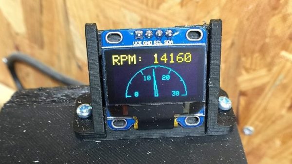
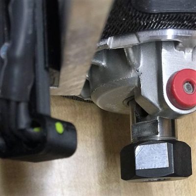
The CNC router in question is the popular Sienci, and the 3D-printed brackets for the photodiode and LED are somewhat specific for that machine. But [tmbarbour] has included STL files in his exhaustively detailed write-up, so modifying them to fit another machine should be easy. The sensor hangs down just far enough to watch a reflector on one of the flats of the collet nut; we’d worry about the reflector surviving tool changes, but it’s just a piece of shiny tape that’s easily replaced.  The sensor feeds into a DIO pin on a Nano, and a small OLED display shows a digital readout along with an analog gauge. The display update speed is decent — not too laggy. Impressive build overall, and we like the idea of using a piece of PLA filament as a rivet to hold the diodes into the sensor arm.

Want to measure machine speed but don’t have a 3D printer? No worries — a 2D-printed color-shifting tach can work too.

Continue reading “Optical Tach Addresses The Need For Spindle Speed Control”

Quick Arduino Hack Lets Tach-less Car Display Shift Points

A tachometer used to be an accessory added to the dash of only the sportiest of cars, but now they’re pretty much standard equipment on everything from sleek coupes to the family truckster. If your daily driver was born without a tach, fear not – a simple Arduino tachometer is well within your reach.

The tach-less vehicle in question is [deepsyx]’s Opel Astra, which from the video below seems to have the pep and manual transmission that would make a tach especially useful. Eschewing the traditional analog meter display or even a digital readout, [deepsyx] opted to indicate shift points with four LEDs mounted to a scrap of old credit card. The first LED lights at 4000 RPM, with subsequent LEDs coming on at each 500 RPM increase beyond that. At 5800 RPM, all the LEDs blink as a redline warning.  [Deepsyx] even provides a serial output of the smoothed RPM value, so logging of RPM data is a possible future enhancement.

The project is sensing engine speed using the coil trigger signal – a signal sent from the Engine Control Unit (ECU) which tells one of the ignition coilpacks to fire. The high voltage signal from the coilpack passes on to the spark plug, which ignites the air-fuel mixture in that cylinder. This is a good way to determine engine RPM without mechanical modifications to the car. Just make sure you modify the code for the correct number of cylinders in your vehicle.

Simple, cheap, effective – even if it is more of a shift point indicator than true tachometer, it gets the job done. But if you’re looking for a more traditional display and have a more recent vintage car, this sweeping LED tachometer might suit you more.

Continue reading “Quick Arduino Hack Lets Tach-less Car Display Shift Points”

Retrotechtacular: The J-57 Afterburner Engine

The J-57 afterburner engine appeared in many airplanes of notable make, including the F-101, -102, and -103. This USAF training film shows the parts of the J-57, explains the complex process by which the engine produces thrust, and describes some maintenance and troubleshooting procedures.

The name of this game is high performance. Precision thrust requires careful rigging of the engine’s fuel control linkage through a process called trimming. Here, the engine fuel control is adjusted with regard to several different RPM readings as prescribed in the manual.

One of the worst things that can happen to a J-57 is known as overtemping. This refers to high EGT, or exhaust gas temperature. If EGT is too high, the air-fuel ratio is not ideal. Troubleshooting a case of high EGT should begin with a check of the lines and the anti-icing valve. If the lines are good and the valve is closed, the instruments should be checked for accuracy. If they’re okay, then it’s time for a pre-trimming inspection.

In addition to EGT, engine performance is judged by RPM and PP7, the turbine discharge pressure. If RPM and PP7 are within spec and the EGT is still high, the engine must be pulled. It should be inspected for leaks and hot spots, and the seals should be examined thoroughly for cracks and burns. The cause for high EGT may be just one thing, or it could be several small problems. This film encourages the user to RTFM, which we think is great advice in general.

Continue reading “Retrotechtacular: The J-57 Afterburner Engine”