Most often ultrasonic transducers are used for distance measurements, and in the DIY world, usually as a way for robots to detect obstacles. But for a weekend project, [Vinod.S] took the ultrasonic transmitter and receiver from a distance-meter module and used amplitude modulation to send music ultrasonically from his laptop to a speaker, essentially transmitting and receiving silent, modulated sounds waves.
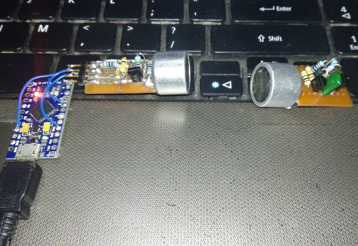
For the transmitter, he turned an Arduino Pro Micro into a USB sound card which he could plug into his laptop. That outputs both the audio signal and a 40 kHz carrier signal, implemented using the Arduino’s Timer1. Those go to a circuit board he designed which modulates the carrier with the audio signal using a single transistor and then sends the result out the ultrasonic transmitter.
He took care to transmit a clear signal by watching the modulated wave on an oscilloscope, looking for over-modulation and clipping while adjusting the values of resistors located between the transistor, a 5 V from the Arduino and the transmitter.
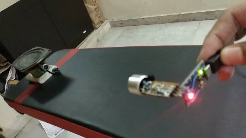
He designed the receiver side with equal care. Conceptually the circuit there is simple, consisting of the ultrasonic receiver, followed by a transistor amplifier for the modulated wave, then a diode for demodulation, another transistor amplifier, and lastly a class-D amplifier before going to a speaker.
Due to the low 40 kHz carrier frequency, the sound lacks the higher audio frequencies. But as a result of the effort he put into tuning the circuits, the sound is loud and clear. Check out the video below for an overview and to listen to the sound for yourself. Warning: Before there’s a storm of comments, yes the video’s shaky, but we think the quality of the hack more than makes up for it.
What else can you do with the ultrasonic transducers? You could wire a bunch of them to a Raspberry Pi to make a piano interface. Or you could use a larger transducer to make an affordable ultrasonic soldering iron.


We need a shaky cam waring on that…
Very interesting , I guess wouldn’t be difficult to transmit data as well…
I think that is one way google cast finds nearby tv’s
Data transfer was done already, 2013 for breaking into air-gap computers:
https://arstechnica.com/information-technology/2013/12/scientist-developed-malware-covertly-jumps-air-gaps-using-inaudible-sound/
I wouldn’t mind playing an old zx spectrum tape across it to find out. Maybe shift the frequency down for transit then compensating at the other end.
Cool! Any estimation on possible range?
this is awesome, good job mate!
Could this have been done with the laptop speakers as the ultrasonic transducer?
yes, I just tried last night and it worked, but my laptop cuts off at 45ish kHz so I had to use 30kHz as the carrier wave. you don’t even need the arduino, as you can do the modulation in audacity.
I wonder if this could be done passively…
possibly but not that easier , you have to shift all the frequency range up without crashing it and down again
Like how, I’m having a mental fart. Like noted above with an up converter from the laptop speakers and a microphone plug with transducer, then downconverter using speakers in another radio? Shifting phase would be a RC circuit, other than a mixer requiring an oscillator or maybe advanced IC/FPGA…. hhmmm…
Neat simple system also.
I had the idea last night to use a ELF/VLF antenna directly from the speaker output and speaker input. I’m guessing an AM antenna like ferrite loopstick or even better lower magnetic permeability material core tuned for the audio connections optimal range is more passive. Would be interesting to determine the most directional smallest design. Like a spiral conical core and winding maybe?
Now, to implement this in Cuban hotel rooms!
(Just the transmitter, playing patriotic US music)
B^)
>”Due to the low 40 kHz carrier frequency, the sound lacks the higher audio frequencies.”
That’s not the issue. The RC filter is set at 1.6 kHz which is mainly responsible for the poor high frequency response.
The reason is that a simple RC lowpass filter drops only -20dB per decade, so in order to get rid of the 62.5 kHz PWM frequency you have to set the filter really low. At 6.2 kHz cutoff frequency, you still got 10% of the original PWM signal present in the output.
To get better fidelity out of the system, you might as well transmit the PWM signal as-is because the loudspeaker won’t play it back. It’s only a problem if you have proper speakers, or really tiny tinny speakers because those can reach ultrasound frequencies and may burn with you pushing a 62 kHz square wave through.
Or, to put it otherwise, the loudspeaker sees the PWM waveform as a full swing 5 Volt peak to peak square wave and tries to play it back. A common midrange speaker has too much impedance at that frequency to do anything – it just blocks the current – but a small speaker like an earbud or a tweeter will pull watts of power and burn your tiny amplifier as well as itself.
That’s why you filter the PWM out, and in this case it means anything up from 1.5 kHz gets attenuated. A critically damped RLC filter would drop -40 dB per decade and allow you to lift the cutoff frequency to around 6-8 kHz without letting too much of the PWM frequency through.
If you want to go hi-fi with this, you need second and third order filters on both ends.
Maybe better a 40kHz PWM signal then, right? I mean, with 40kHz transducers, that’s what would pass.
Exactly, and the signal can be reconstructed at the recieving end, which achieves automatic gain control.
You could probably get away with transmitting at 44.1 kHz as well.
You can modulate your audio in audacity, you can even do FM. My laptop will happily play up to 45ish kHz from the internal speares, and I guess most laptops will do. you can use a good mic on another computer with some SDR and you can easily demodulate the audio and even get full 20khz audio from it. alternatively you can use an audio amp (my akai goes all the way up to the 45kHz my laptop outputs) and use a wire as an antenna instead of the speakers, and you’ll have your own LF radio wich you can pick up using a wire connected to a good soundcard. 30kHz seemed to be the best carrier frequency for me, since the laptop refuses to play anything above 45kHz even after setting the output sampling rate to 192kHz. I tested all of this and everything worked very nicely, to my surprise.
Awesome Steve, Vinod.S, someone, et.al.! ISM devices and limits too! Someone, you can do an instructional video and have a write up on HaD now.
I’m confident you recall or have seen the article that starts at page 49, not quite ultrasonic… though gives a general idea of what is being thought out with COTS devices:
http://www.americanradiohistory.com/Archive-Elementary-Electronics/1970/Elementary-Electronics-1972-05-06.pdf
I wonder if this will be picked up by the brain if using a 15kHz carrier frequency as noted in V2K like Silent Sound subliminal Mind Control whether Spread Spectrum or not. The 40kHz carrier signal seems to align with the Neurophone also if anyone didn’t notice: http://www.eucach.org/v2k_voice_to_skull.html
Did you ever find out? My ex has the akai setup and he was talking to someone without phone earbuds etc. Like v2k.