Sometimes you have to switch a light. Maybe it’s an LED but sometimes it’s mains-powered. That’s not too hard, a transistor and a relay should do it. If you have to switch more lights, that’s not too bad either, as long as your microcontroller has enough free GPIOs. But, if you need to switch a large number of lights, like 256 of them, for example, you’re going to need something else.
[Jan]’s project didn’t switch quite that many lights, but 157 of them is still enough of a chore to need a creative solution so he decided to use a 256-bit shift register to do the legwork. The whole thing is powered by a NodeMCU ESP8266 and was professionally built on DIN rails in a metal enclosure.
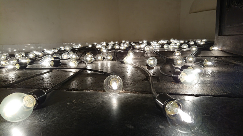
The build is interesting, both from a technical point of view and from an artistic one. It looks like it uses more than a mile of wiring, too. The source code is also available on the project page if you happen to have a need for switching a huge number of lightbulbs. Incandescent blulbs aren’t only good for art installations and lamps, though, they can also be used in interesting oscillator circuits too.


This is an easy and quick problem to solve with about a €5000 of DMX dimmer packs (plus, realistically, about the same again on other cabling and packaging, and labour). So he came out well ahead with his €1700 cost (if you count the 3 months of work as free).
In the days of 8 bit microcontrollers with 16 or less address lines, shift registers were used all the time. The classical dot led store Window sign 80’s Style had a whole board stacked with CD4021 8 bit shift register ICs.
“and was professionally built on DIN rails in a metal enclosure.” I had to control 24 individual rgb led’s (72 led’s, 96 wires), It’s enough of a chore to strip, clean and prepare so many cables outdoors (and they were rather short from wall to control box, so not too much space for working), after about 20 you begin to see why professional solutions are so great – because at that scale it’s the only way to make it manageable. Rat’s nest won’t do here and may cause fires.
This could be done with 300€ of SSR modules
Sure, and a 555 too….
SSRs might replace the relay boards: €200 of the total cost. The rest of the wiring, case, dimmers, breakers, power supplies, etc. still need to be got. Doing it all for €1700 (€11/channel) for a one-off system is pretty good. I’d probably charge that much for the cabling alone.
80 Sonoff wifi switches with custom firmware?
That’s interesting. Or, since they’re so cheap, skip the relay boards and go one Sonoff basic per wire strand. I don’t want to have to program them all, but presumably you could batch it somehow. You’d need a good WiFi router — I’ve heard of the cheapo houselhold ones sagging after 30 clients or so…
But yeah. This is absurd and could actually work.
Probably not via regular wifi, but ESP-NOW! should work.
At the moment I wrote the comment I knew that there are 2 port Sonoff switches. Now they have 4 port with DIN railing, so 40 of those would suffice in this installation.
The suggestion was with the intended usage of turning on and off one bulb daily at 12:00. If the turning bulbs on and off isn’t in real time, then not all of 40/80 or 157 Sonoff basic have to be connected to the wireless at the same time. You have them wake up every 60 minutes/3 hours/6 hours, connect to wireless, get correct time (if RTC drifts), and ask if it’s their turn to turn on/off and at what moment in time, disconnect from wireless. No more than a few wifi clients at the time.
If real time was needed, the question is if it’s live due to sensors or it’s preprogrammed – for preprogrammed in an art installation a professional DMX equipment is maybe too much, but a bunch of Arduinos with off the shelf relay boards is easy to control through Vixen ( https://hackaday.com/2015/11/19/akibas-awesome-lighting-tutorial/ )
Just from a reliability point of view SSRs would be better used here than relays.
Biggest reliability failure will be crosstalk/interference in the ‘595 serial line. One extra glock glitch, and everything ends up shifted by one bit.
I think anytime that a “Glock” glitches, there is going to be a lot of talk…
B^)
In the 80’s there was a disco in Beaverton Or.named Earthquake Ethel’s. The interior was encircled with panels of white incandescent lamps that ran wild patterns and moving images synced to the music.
I was admiring the light show and happened to run into the designer of the system. I don’t remember his first name, but he identified himself as Howard Vollum’s son.
The system was based on a PDP-8 with custom high speed coax channel drivers. The bit serial data over these lines was loaded into shift registers which drove an SCR embedded in the socket of the lamp.
Sadly, Disco died ( just kidding ) and the place was demolished.
I don’t know which PDP-8, It had a 1/2 height white front panel with 2 switches in a small rack,
Jim
Wait…
Are saying-
1- disco is dead
2- you should not be sad that disco is dead
Choose your answer carefully sir! VERY CAREFULLY!
In a home control project I’m working on (and will write up at some point), I use a bunch of the same SainSmart 16-channel relay boards that [Jan] used. Originally I used several Arduino Megas to drive them, but then discovered this ???????????????????????????????? 48-channel, $25 mux shield (http://mayhewlabs.com/products/mux-shield-2) and life has been ducky ever since. One mux shield drives three of the 16-relay boards! Still takes 11 Arduino pins to control it, but you can cut that down to 7 if you don’t need programmable control over whether the connections are inputs or outputs.
BUT, there’s a ???????????????? simpler way to do [Jan]’s art project. You can buy tiny, supercheap WS2812 boards (from AliExpress, for example) without the RGB LEDs installed (or, if you can’t find those, unsolder the LED from a complete one), and use them to control the relay boards (by setting one or more of the three PWM channels full on or full off. You might need a small capacitor across the relay coil). I use those WS2812 boards in another project for driving high-power MOSFET-based light dimmers. It takes just an optoisolater, a couple of resistors, and a MOSFET for each dimmer.
If I were doing something similar to [Jan]’s thingy, I would buy or build a bunch of inexpensive dimmers (again, MOSFETs work fine) and mount one, plus its WS2812 controller, in each light socket. Then you could have a LONG daisychain of high-power, individually-controlled incandescent lights and avoid that big (and no doubt expensive) pile of cables that he has–????????????, you could control the brightness of each lamp instead of just switching it on & off (which can’t be done with [Jan]’s relay-based setup). Takes just four wires–two fat ones for high-current +120VDC & common, and two skinny ones for data and +5VDC (to both run the WS2812s and bias the MOSFETs).
Yeah, this simple MOSFET dimmer has to run on DC, not AC–I use a big bridge rectifier connected directly to the mains. No filter capacitor or other power supply circuitry is required. You’d think it would generate a shïtload of electrical noise, but I haven’t noticed any problems even when I’m running kilowatts of lights. ???????? ???????????????????????? you should use an isolation transformer on the mains (you can get a nice 1kW toroidal one for about $160 from Amazon), but I don’t and I’m still alive to write this. If you use the isolation transformer, then you can actually ground the “common” mentioned above–otherwise, just remember that both the +120VDC and the common are hot to an actual AC ground/neutral.
I don’t know why I’ve never seen this WS2812 hack anywhere else–it seems kinda obvious to me. Three PWM outputs for each serially-connected chip that costs just pennies a piece!
And speaking of WS2812 hacks, here’s another very useful one: If there’s more than a couple of meters between your controller (Arduino or whatever) and the first WS2812 in the string, then the WS2812s aren’t going to work reliably. You can easily fix that by putting a single WS2812 (with or without an LED attached) right at the controller and using it as a line driver for a quite long cable. Just remember to account for it in your code (it’s device #1 in the string, obviously).