For those of us who like to wrangle electrons from time to time, there are some exceptional deals out there for low (or at least lower) cost imported test equipment. If you’re willing to part with a few hundred dollars US, you can get some serious hardware that a decade ago would have been effectively outside the reach of the hobbyist. Right now you can order a four channel oscilloscope for less than what a new Xbox costs; but which one you’ll rack up more hours staring at slack-jawed is up to you.
Of course, these “cheap” pieces of equipment aren’t always perfect. [Paul Lutus] was pretty happy with his relatively affordable Siglent SDG 1025 Arbitrary Function Generator, but found its accuracy to be a bit lacking. Fortunately, the function generator accepts an external clock which can be used to increase its accuracy, so he decided to build one.
[Paul] starts off by going over the different options he considered for this project, essentially boiling down to whether or not he wanted to jump through the extra hoops required for an oven-controlled crystal oscillator (OCXO). But the decision was effectively made for him when his first attempt at using a more simplistic temperature controlled oscillator failed due to an unfortunate misjudgment in terms of package size.
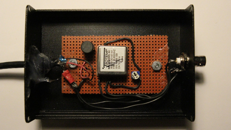
In the end, he decided to spring for the OCXO, and was able to use the USB port on the front panel of the SDG 1025 to provide the power necessary for the crystal to warm up and remain at operating temperature. After he got the oscillator powered, he just needed to put it in a suitable metal enclosure (to cut down external interference) and calibrate it. [Paul] cleverly used the NIST WWV broadcast and his ears to find when his frequency standard overlapped that of the source, therefore verifying it was at 10 MHz.
Hackers love accuracy, and accordingly, we’ve seen a number of frequency standard builds ranging from extremely cheap to luxuriously overkill.


If you’d like to know more about Paul and his early work on the Apple II, check out this interview:
http://www.open-apple.net/index.php?s=Paul+lutus+
Two lines have me worried –
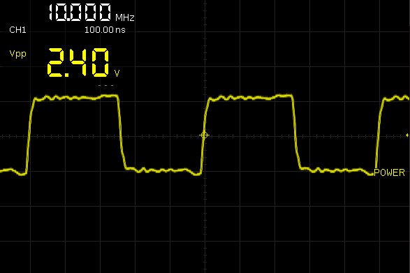
“The open-circuit amplitude is about 8V peak-to-peak.”
and
“Because it has a BNC output connector, this project should work with most systems that accept a 10 MHz external clock (like the HackRf One device), so my Siglent generator is just one of many applications for such a frequency standard.”
There is no protection for from connecting an incomparable clock to the HackRF schematic:
https://i.imgur.com/vs9qwki.jpg (from : https://github.com/mossmann/hackrf/blob/master/doc/hardware/hackrf-one-schematic.pdf )
And the datasheet for the Si5351C (Programmable Clock Generator) explicitly specifies -0.1 to 3.6 volts as minimum and maximum voltages.
https://i.imgur.com/57jIuh1.jpg
So the “Simple 10 MHz Frequency Standard”, without additional circuitry, if connected directly to a HackRF will cause permanent damage.
The two problems are the voltage is 8 volts peak to peak instead of 0 volts to 3.3 volts and the voltage is centered around DC instead of 1.65 volts. The HackRF expects 3.3 V CMOS Logic Levels ( https://learn.sparkfun.com/tutorials/logic-levels/33-v-cmos-logic-levels ) on the clock in, anything else will likely cause permanent damage.
Good one!. I’m just getting my feet wet in Ham radio myself after a career in computer science. Been looking for an OCXO like this for my cheapie function generator so this is very timely for me. Now if I can just get my rig on the air…
I see your OCXO and rise a rubidium frequency standard.
Been there and done that. :) A few years ago, I needed a precision frequency reference to calibrate a frequency generator design that I make available for purchase. I had nothing in my arsenal to provide an accurate frequency reference. Back in the late 70’s, I once worked for OPTOELECTRONICS out of Fort Lauderdale, Florida. They were making TCXO’s for their frequency counter line and had a WWV source for calibration and testing, so that was my 1st thought, go WWV but I lacked the equipment for that as well. That meant I’d have to design a receiver and well, Florida is a bit of a distance from Colorado, so I decided that a local reference would have to do. I settled on 10MHz as the reference frequency.
In my search for other projects of the like, I came across the rubidium oscillator and acquired one on eBay for about US$70. It needed +18 volts to operate but a laptop power-supply was easy enough to obtain for that. I also decided to look at an OCXO, the same ISOTEMP type as shown in the above photo. I acquired one on eBay for about US$20. There were other features that I wanted, a programmable divide-by-N output as well as a programmable DDS output, so I designed an ATmega32U4 around it all. I found a nice aluminum enclosure for it all at SKYCRAFT in Orlando, Florida.
The OCXO required a warm-up time as did the rubidium oscillator. I used an AD590 temperature sensor to detect just when the OCXO is “warm enough”. The rubidium oscillator has a “ready” pin to signal that condition.
I figured that I since the OCXO had a VCO adjust pin, I could control it via a poor-man’s DAC from the AVR and then I could just use the Rubidium oscillator as a precision reference source driving a 74HC4046. Under software, I look at the “lock detect” output from the 74HC4046 over a period of 10 seconds and then adjust the OCXO’s VCO adjust pin to calibrate it, then check again until there is a zero-beat between the two sources. This method seems to work very well
Overall, the design works as intended. However, I found that the accuracy of the OCXO was good enough that repeated calibration attempts over the years ALWAYS showed that no calibration of the OCXO was ever required. In my application, using a rubidium oscillator wasn’t actually necessary because the OCXO was good enough for my purposes. However, working with the rubidium oscillator was certainly fun! :)
I never had a chance to post this particular project, so no links to the design and code are available at this time.
The datasheet for the ISOTEMP OCXO-131 series shows its “R.F. Output” is “HCMOS” with 0.3V to 4.5V levels @ 5 volts supply but the OCX-143 (OP is using) shows ~6 Vpp sine wave “unloaded”, so this particular OCXO can be loaded with a 50 ohm load then a simple HCMOS digital buffer could be used to drive a digital load for the frequency generators and counters.
Peace and blessings.