We recently posted about a spectacular 3D-printer fire that was thankfully caught and extinguished before spreading to the hacker’s house or injuring his family. Analyzing the remains of the printer, the hacker determined that the fire was caused when a loose grub screw let the extruder’s heater cartridge fall out and touch the ABS fan shroud. It ran full-on and set things on fire.
A number of us have similar 3D printers, so the comments for this article were understandably lively, but one comment stood out by listing a number of best practices for wiring, including the use of ferrules. In particular, many 3D printers connect the heated bed, which draws a lot of current, with screw terminals to the motherboard. While not the cause of the fire in the original post, melted terminal blocks are a common complaint with many DIY 3D printer kits, and one reason is that simply jamming thick stranded wire into a screw terminal and hoping for the best can result in increased resistance, and heat, at the joint. In such situations, the absolutely right thing to do is to crimp on a ferrule. So let’s talk about that.
A Series of Tubes
So what is a ferrule anyway? In general, any kind of band or clamp that’s used to attach, reinforce, or secure objects to each other. That’s a broad definition that covers everything from the aglets applied to shoelace ends to prevent unraveling to the stout metal clamps used to connect wire ropes together. But in the world of electrical wiring, ferrules have a more specific definition, and very different purposes than ferrules used for purely mechanical applications.
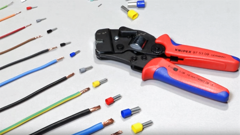
An electrical wiring ferrule is a soft metal tube that is crimped onto the end of a stranded wire to improve the wire’s connection characteristics. Most ferrules are made of copper, which is usually plated with tin. The ferrule is sized for a specific gauge of wire, both in terms of its diameter and its length. A ferrule is not just a simple cylinder, though — it has a lip or flare formed into one end that serves to collect and consolidate the individual strands of the wire as they are inserted into the ferruule.
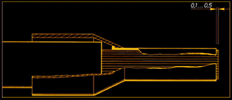
The flare in most ferrules is not immediately apparent because it’s usually encased in a conical plastic cable entry sleeve. This sleeve acts as a transition between the insulation of the wire and the ferrule itself, and also serves to corral all those loose strands into the lumen of the ferrule. Unlike in more traditional crimp connections, the plastic sleeve of a ferrule is not compressed during installation. It stays intact around the insulation, and provides some measure of strain relief after installation by moving the bend radius of the wire away from the end of the insulation. Most ferrule sleeves are color coded for wire size in the DIN 46228 standard, which confusingly has two different codes, French and German, for the same cross-sectional area in square millimeters.
Making Stranded Wire Solid
If it sounds like ferrules are more a European thing than an American one, that’s with good reason. In order to get CE certification, electrical equipment must terminate stranded wire entering a screw or spring terminal with ferrules. There’s no such regulation in the US, and so it’s not common to see ferrules used in American equipment. But ferrules have specific advantages that are hard to deny, and their adoption appears to be spreading because they make good engineering sense.
To understand the principle, clip a small piece of insulated stranded wire of any gauge. Stranded wire is flexible, which is one of the reasons it’s used rather than solid wire in mobile applications and where vibration can occur. But it’s still somewhat stiff thanks in part to the insulation, which wraps the strands of the conductor, keeps them all in intimate contact, and maintains the twist, or lay, of the separate strands. Now strip off a bit of insulation from one end. You’ll notice that in most cases, the lay of the strands is at least partially disturbed — they untwist a little. Strip off more insulation and the strands get more and more separated. Take off all the insulation and the conductor will lose all structural integrity, falling into individual strands.
This is the essential problem that ferrules solve: they maintain the close association of strands in the conductor after the wire has been stripped and allow the connection to conduct its full rated current. Without ferrules, stripped stranded wires compressed in screw terminals tend to splay apart, reducing the number of individual strands that are in firm contact with the terminal. The resistance of such terminations is much higher than properly ferruled connections.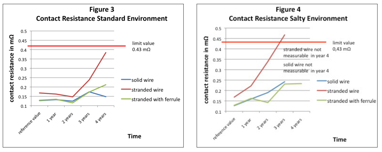 Stranded wires with ferrules perform much better than without them. Source: Weidmüller Interface GmbH & Co. KG
Squeezing Your Problems Away
There’s more to a ferruled connection than reduced resistance, though. Like other crimped connections, the strands inside a properly applied ferrule undergo tremendous pressure, in the process stretching axially and deforming radially. The stretching action tends to disrupt and displace surface oxidation on the strands, while the radial compression tends to remove the air spaces between the strands. These tend to make the crimped connection better at resisting oxidation than uncrimped wire, increasing the longevity of the connection.
So are ferrules the way to go for the home gamer? On the whole, I’d say yes. Ferrules have obvious advantages over plain stranded wire, and in high-current applications, I would insist on using them with screw terminals or anywhere that the strain relief into the shielding is helpful. Plus, they lend a clean, professional look to a project, so even if the application is non-critical, I tend to include them on my stranded wire connections. It’s not without its cost to tool up for ferrules, of course, but at $30 for a kit with an assortment of ferrules and a proper ratcheting crimp tool, it’s not too bad.
Thanks to [NobodyInParticular] for suggesting this story.
[Featued images: KNIPEX, Ferrules Direct]


“Stranded wire is flexible, which is one of the reasons it’s used rather than solid wire in mobile applications and where vibration can occur. ”
And can still break, just takes longer. I believe it’s also a softer copper as well.
No link to the talk you posted a few weeks ago about wiring a pipe organ and using ferrules? That video got me into ferrules and now I love them.
Can you provide some good recommendations for a tool?
Phoenix Contact makes an excellent tool that includes magazines (like a gun) preloaded with various sized ferrules that slide into the tool.
I checked it out, they were 900.00 dollars
Used Weidmuller PZ 4 are often available on eBay for around $30. Quality tools with replaceable dies. They’ll do wire sizes from 12 to 21 AWG.
weiland is a good tool. We use them is small lot production < 1000 pieces
With most of connectors a cheap crimping tool from china/ebay will server you more than admirably.
– For Ferullas simple 4 jaw is good enough(6 jaw is technically better, but with 4 jaw you get a nice square, which can make a difference of you being able to fit slightly oversized wire in the PCB screw terminal) for round terminal blocks used in AC installations 6 jaw would be a better fit.
– Then for blade connectors get the set with exchangeable jaws like Paron in china you get a crimper with 4 jaws and a thin wire stripper in a nice pouch
– JST connectors – especially the small pitched ones are story of its own and you need a narrow tool to be able to do anything decent with them like Engineer 09 or proper ones from JST but they are ($400+)
– IDC(Insinuation Displacement Connectors) can be easily done without tool. But you can get simple pliers with 2 flat surfaces to simplify the tooling.
– Most name-brand connector manufactures tools have astronomical prices but some have tools specifically for connector for much more affordable prices(TE connectivity)
– When you move to semi-serial production 50+ pieces consider also dirty cable a service offered by dirty PCB
https://hackaday.com/2017/06/25/dirty-now-does-cables/ and with more explanation about popular connectors on this link
http://dangerousprototypes.com/blog/2017/06/22/dirty-cables-whats-in-that-pile/
It is always good to consider the type of material when designing the connection system(Gold is not always the most appropriate), and the voltage generated between 2 metals can create joints inappropriate for long term installment https://blog.samtec.com/post/dissimilar-metals-in-mating-connectors/
If you want to brush on the basic mechanic of connector crimping check the hackaday article about it https://hackaday.com/2017/02/09/good-in-a-pinch-the-physics-of-crimped-connections/
spoiler crimping = cold-welding
If you want to get really in to details then there is a really good book from Wurth elektronik
http://www.we-online.com/web/en/electronic_components/produkte_pb/fachbuecher/Trilogie_der_Steckverbinder.php
1 thing to remember, DO NOT SOLDER crimped connectors
bonus: If you master all of the above, you can get a job without a problem in any major industry, and there is a certain beauty in properly crimped connectors
Knipex ref 97 72 180 pliers. Paid something like 25€, used them to crimp approximately 300 cable ends, and I’ll use them a lot next week to rewire the electronics in a CNC router. Don’t buy the cheapest ferrules, though, buy branded ones (schneider for example).
pressmaster MCT frame and the right plug-in insert thingie (die). the frame is about $70 and dies are $50ish, give or take. this is the best thing I’ve found, from reading eevblog and trying it out. it does molex kk connectors and all kinds of stuff, just buy the right die insert. pressmaster sells under many names, so find it via photo, then see what other names its listed under, for you.
https://www.amazon.com/MCT-FRAME-Pressmaster-Mobile-Frame/dp/B00IEBLO7K
that’s the frame (MCT series) I was referring to. fyi
sorry, one more link:
https://www.amazon.com/Wiha-43192-Porta-Crimp-Professional-Crimping/dp/B0015BR7P4
that’s where its re-branded. wiha had nothing to do with that, but huge markup! best to avoid that situation; get whatever name you can find on that MCT that saves you money. the dies are all the same and there are no brands on those, just pressmaster (from what I’ve seen; I have about 3 or 4 dies and that covers all my needs).
https://www.amazon.com/gp/product/B00H950AK4/ is what I use at home. It’s far cheaper but seems identical to the ones sold by ferrulesdirect.com (which is the vendor we use where I work).
Always be careful with tools, and especially crimpers. What appears to be identical from low-ish res pics on your computer could mean the dies are craptastic between the amazon version and the one sold by a reputable vendor. The dies are the most important part : if they are not well designed and manufactured, you can’t rely 100% on the quality of your crimp, and it defeats all purpose of using a ferrule.
Unior 514 and gedore 8133 are nice for quick crimping if you don’t want to carry a lot of tools in your bag. In workshop it’s good to have dedicated tools. At work we have gedore and knipex and they work fine last 7 years.
What about tinning the stranded wire end? How does this compare with a ferrule? It also removes oxidation and eliminates air spaces around the strands.
I’ve always understood that this is not a good idea because solder is actually rather high resistance comparatively speaking.
It works but there is no mechanical strain releif which is arguably most important. I’ve seen way too many tinned wire ends which have broken off quite easily at the transition between tinned and non tinned part of the wire.
Worse than that, the end of the solder tinning provides a stress point making it more likely to break
Worse even, solder is malleable and not springy, so even if the screw is fastened tightly, any mechanical deformation can cause the connection to become microscopically loose.
Worse than that, the end of the solder tinning provides a stress point making it more likely to break
http://reprap.org/wiki/Wire_termination_for_screw_terminals
NASA TECHNICAL STANDARD
CRIMPING, INTERCONNECTING CABLES, HARNESSES, AND WIRING
https://prod.nais.nasa.gov/eps/eps_data/145968-OTHER-002-006.pdf
If I remember correctly, it makes the part of the wire where the solder ends more susceptible to breaking. So you’ll have a nice firm tip but the wire breaks off quicker.
Yep. The solder can wick up the strands into the insulated portion and become a weak point for fatigue.
The NASA soldering bible, feature here a few months ago, explicitly says not to let the solder wick up closer than 1-2 mm before the insulation on the wire. What you do when wires need to connect to mowing things is to use Litze wire( just the cheaper, not individually insulated strands type) as it is made of hundreds of hair thin wires loosely wound. Then you have a wire pliable enough not to break.
Litz wire, by definition, IS a bundle of individually-insulated wires. There is no “cheap version” with uninsulated strands because that defeats the purpose of Litz wire. You just want high strand count or “ultra flexible” wire. It doesn’t do all that much for the weak spot produced by soldering, though.
In any event, that’s not even the reason you’re not supposed to solder wires in a screw terminal. If it was, it’d be fine as long as the wire wasn’t flexing or being vibrated near the terminal. The problem is that solder creeps (“cold flow”) pretty easily. It deforms over time, the joint loses compression, and then you have a loose connection and all that entails.
“What you do when wires need to connect to mowing things…”
I didn’t realize NASA was so involved with harvesting hay or cutting grass!
B^)
No good. It creates a weak point immediately after the solder blob, and flexing the cable a bit too much will likely damage the cable at this precise point. The sleeve(ferrule) with its plastic end is much more easy on the cable even if the cable is pulled with force.
Never tin a wire end that goes into a screw terminal.
The tin is not really solid, but will deform over time. So a connection that is screwed tight on installation will get loose over time.
Loose connection -> higher resistance -> higher temperature -> less solid tin -> more loose connection…
You see where that’s going ;)
Additionally the tin will flow into the insulation and create a hard spot somewhere away from the terminal – and if you’re unlucky this is where single strands of wire start to break, leading to an invisible defect.
The main problem, apart from tin or the classical tin+lead mixture being too soft, is that tin is “cold flows” away from the screw by thermal cycling and stress and you will end up with rather big contact resistance sooner or later.
Third reason that I hear mentioned against soldering is that solder is too soft and the screw connection will loosen over time.
Cold flowing under pressure is the same reason why old aluminium mains wiring is so dangerous. The connection becomes loose over time and resistance goes up + bad connections cause arcing.
I’ve never liked finding that in the field. The solder is rock hard and slippery so the terminal block can’t compress and hold onto it like softer stranded copper. The ferrule crimper puts serrations on the crimp so it grabs a lot better than solder.
No good for high currents. The solder softens with heat and then the entire wire end collapses.
soldering is no good idea. The solder would break due to physical stress.
Tinning wire for screw terminals is a bad idea, as the solder will displace slightly under pressure even at room temperature, and as it temperature cycles, will flow from the joint, reducing the contact area and increasing resistance, and thus heat, causing a positive feedback effect.
Tinning is soft compared to bare copper.
So Screws might come lose with time, faster than with ferrules or lugs.
i know that in europe it was common to tin stranded wire until many devices faild or burned, now crimping is the thing.
poses a problem with strain relief… usually breaks exactly where the solder ends, because it allows a very sharp bend (soldered wire is stiff, non-soldered is not….
Tinning a stranded wire end makes the part of the wire behind the tinning brittle.
I would never recommend to solder wire. Specially if there is vibration or even movement your cable would break after a short period.
In a pinch, in the field, with low currents when no ferrules are available I have been known to fold the multi strands back and push the entire batch into the cage type screw terminal. This provides a strain relief, and arrests any stray whiskers. It has proved successful over many years, however the contact area will be reduced, so not suitable for high current situations. The system has also proved unsuccessful on sold cored cable, sometimes resulting in intermittent connections.
Wow. A lot of responses, all of which say don’t, and plenty of disagreement as to why.
So, I’ll throw in my two cents.
Don’t.
Several of the previous reasons are applicable, but there are other reasons as well. Aside from the stress riser where the solder transitions to the stranding, and the cold flow (the soldered end has lower inherent resistance than the base wire, but the resistance of contact is proper area and pressure is not maintained will cause heating), other significant issues are latent corrosive effects from some fluxes, the change in mechanical properties of the solder and the diffusion alloy interface where the solder meets the copper due to the initial crushing (which will likely include cracking), the loss of mobility and ductility due to the solid nature of the tinned end (as compared to a round solid wire or the stranded wire… I can’t think of a better way to word this), and potential long term effects due to environment (chemical) that the tinned material will be subject to due to the differential material at the solder boundary and the physical/structural changes due to cold working under the screw.
Now, the funny thing is that is you use the old school soldered in brass grommet properly, you will likely get 100 or more years of service. But good luck finding a source today, and the labour involved in properly fitting these is more than it is worth.
at the school I attended “old school” persons not using a simple moniker instructed us, that a connection should be both electrically and mechanically secure before solder is applied, and the solder shouldn’t be relied on to carry current. Your suggestion fails on three counts. The fourth is unreliable because that simple work could have been done at any time during that hyperbolic 100 years.
The solder tends to flow away from the point of pressure, leading to a loose joint.
Soldering before crimpint or inserting into a screw-down terminal is expressly forbidden in the Australian wiring rules for this reason.
Apart from the higher resistance and the increased likelihood to breaking at the end of the tinned portion there is also the problem of the solder deforming under stress over time. tin/lead has a weird property that it’ll creep at any temperature. (See also the No.9 “L-delay” Pencil detonator. A stressed connection that makes good contact at first could therefor loose contact over time, leading to increased resistance and overheating. I’ve seen some reports that conclude using bare wire in a terminal is actually better than tinning it because it’s less likely to lose contact unexpectedly.
Solder is soft, so over time it will deform and loosen the connection. Then the surface of the solder will oxidize, making an insulating coating. Just thermal cycling is enough to cause the connection to loosen rather quickly.
The wire also becomes very stiff right up to the point where the solder ends, causing a stress point.
In case anyone is wondering, you’re not getting the Knipex ferrule crimper for $30. They sell for $200+.
I was actually scrolling down to say this. I use a $300 Knipex Ferrule Crimper. I’ve seen a lawsuit where a company sued a contractor because every connection in a 300 i/o point line had to be re-terminated because their new electrician brought in his cheap crimp tool instead of supplying him with industrial grade equipment. I’ve also seen people use cheap wire labels and get sued. Those cheap Paper labels will turn completely white and lose their ink from the heat inside the panel. The customer on that one opened up a panel 3 months after delivery and every wire label had turned white. If you decide to crimp, either use a good crimper or stick to bare wire. A 30 dollar crimp tool is a nightmare-bad recommendation and will introduce failure points at every connection in your project. Intermittent wiring failures are a pain.
I *wondered* what those were called.
I saw them inside of a commercial EVSE I took apart, but have never figured out if they were a thing I could reasonably add to my home-built units. I’ve been, well, jamming the stranded wire in and hoping for the best.
You better believe I’m going to investigate this now…
Some years past, submitted an article to HAD that analyzed the physics per the ‘root cause’ to a neighbor’s garage fire (arduino-controlled system went up in flames), and used the performance and construction requirements of national versions of some common product safety standards (IEC60335-x, IEC60950-1, IEC61010-1, and IEC60079-x) to demonstrate the various problems with the failed system. Crickets. Have occasionally posted some comments on some HAD projects that had egregious examples of fire and shock hazards. Responses to my comments varied in tone from ennui to hostile. Other comments were apparently censored. To their credit, current HAD writers and editors seem less likely to censor and ignore comments and articles having significant dose of safety engineering, EMC, and regulatory content. But that ship has sailed, and thus the ‘maker’ community got off to a rather rough start.
In any case, the real danger is that if you people keep doing stupid shit, the state and municipal governments will find a way to regulate some of your fun pastimes into a criminal activity.
“In any case, the real danger is that if you people keep doing stupid shit, the state and municipal governments will find a way to regulate some of your fun pastimes into a criminal activity.”
Or just raising the costs of our hobby, just like with a lot of other things. People WILL race to the bottom if given half a chance. If it’s not government, then it will be insurance dictating.
+infinity As someone in the Electronics Manufacturing industry professionally now for 27 years, I can attest that I am routinely surprised at some concepts used (or widely accepted) in the DIY/Maker sector. All this talk of 3D Printer fires from cheap eBay or China kits only gets one response from me: well, duh…
The adage of “you get what you pay for” directly applies, but so many are becoming catered/molded by the never ending reduction in price (and quality at some proportional rate) from China that they seem to just not care until it’s too late.
Don’t get me wrong, I hack/make in my off hours and I love spending less for my projects, but there are certain things that I am not willing to sacrifice quality/safety for the sake of expense, even for one off projects.
The ends of shoe laces are secured with aglets. Yes, there is a name for them.
And don’t you ever forget it!
https://www.youtube.com/watch?v=Evcsj1gx1CE
I had to look it up.
Ferrules!
I used to use these all the time in my industrial automation life. A big box of ferrule tips and a nice pair of bootlace crimpers (they compress the tips from four directions at once! amazing!) and you have a happy engineer.
All the terminals were the screwless pushdown kind too, very useful.
They’re great when you have nice BIG electronics cabinets.
Alas, these days everything I build is on 0.1″ spacing, and there’s no terminals that fit the holes or ferrules to suit.
Has anybody seen a pushdown (no screws) terminal design that fits into a single row of 0.1″ spaced holes?
(eg almost every Arduino, Wemos, shield and breakout board on the market)
I would buy a thousand of them in a heartbeat.
Ask and you are served: 0.1″ screwless terminal blocs, for your next arduino shield project:
https://www.pololu.com/category/175/screwless-terminal-blocks
As Josh also says – they *are* 0.1″, but unfortunately need two rows of holes.
(perhaps for mechanical reasons?)
I should try them out and see if they hold together well enough with only a single row engaged, I’m not confident.
I do lots of screw terminals in the things I make and, no, you can’t get decent ones spaced for 2.54mm. I use blocks designed either for 3.5 or 5mm spacing. I use 2 and 3 terminal blocks designed to cascade by sliding them together, so if I need to I can make them into any arbitrary number >2.
I did a quick search on Digikey and found the category of “Terminal Blocks – Wire to Board” and restricted it to 0.1″ and turned up a number of results.
That said, the ones that I was thinking of turn out to have two rows of connections, as they are a little deeper, but you could easily use a proto shield and put them on top of it, no connection required to the second pin row.
It looks like both Molex and Tyco Electric have spring release connectors in 0.1 spacing, but with double rows of connections.
Phoenix has screw terminal blocks in 0.1″, which are single row.
+1 Make my life easier and myself happy. Ferrules!
Did a Search on Mouser:
https://www.mouser.com/Connectors/Terminal-Blocks/Fixed-Terminal-Blocks/_/N-7rqd7?P=1z0wxfyZ1z0wxp6Z1yx0y5wZ1yv73mdZ1yx0y8sZ1yx0y86
What is the benefit going from a 4 sided ferrule crimper to a 5 or higher profile version? It seems like the professional versions are 6 sided.
A square-crimped ferrule fits very well into a square-shaped hole.
A hex-crimped ferrule fits better into a round hole, and should be also ok in a square-shaped hole.
The choice depends on your screw terminals / terminal blocks.
I use ferrules whenever I want the connection to be secure and I know it may carry significant amounts of current. Also, one good thing with ferrules is that you don’t get the same kind of loss of contact pressure over time as you do with twisted multistrand wire, the crimping takes care of that.
Poor contact pressure is a well-known fault scenario, and not unheard of when it comes to causes of electrical fires.
I would say that an assortment of ferrules for standard mains wire sizes and a good pair of crimpers for them is a worthwhile investment for safety.
Just my $.02 worth.
Lets make 3d printer safe again! WIth properly choosed and crimped conectors.
Depends on the situation. It has benefits but I’ve had big issues using them in screw terminal blocks. The block can’t dig in to the wire for a proper hold because it can’t squeeze the ferrule enough so it’s often prone to pulling itself out of the block.
Look where the crimper deposits marks.
In my experience, if you place the ferruled wire so that it faces the screw/pressure point, it grabs a little better.
In the professional setting, ferrules are always used when connecting stranded wires. Makes connections way more secure and easier to do.
Forgot to say that this at least goes for the bigger wires >0,5mm^2
In EU, anything using stranded wire and screw terminals with line voltage – ferrules are mandatory.
That ferrule crimper is useful for other things too. Cut a small piece of soft metal tubing, place two wires into it, one one each end and crimp with the ferrule tool. Now you have a splice that is much more mechanically sound than soldering two wires together. This is a great way to attach leads to an axial resistor to use as a heating element or to a thermal fuse. I like this better than the now-standard heating element approach because with leads coming out of both ends it cannot fall out. Were comercialy produced printers built this way that fire that was referenced could not have happened.
Call em crimps around these here parts and places. Use a bit of solder on the non insulated types and replaceable/heatshrink style for a bit more security and reliability. Could also ‘tin’ wires by themselves when use screw- downs and also snaplock strips. Barrier strips with lock washers helps too. Hot/cold expansion and hostile environments need special attention. Cheap undersized wiring is a hostile environment.
Way too many cheap- ass crimping tools common. If it ain’t got at least one tooth u ain’t biting hard enough and your going to get bit back soon enough.
Tinning wires to put in a screw terminal is a bad idea. Cold solder flow, fast formation of lead oxides at the junction, thermal cycling causing loosened connections due to the difference in thermal expansion of solder and copper/copper alloys…
Lots of good information online contraindicating the soldering of crimped connections before or after crimping.
Just don’t do it.
After crimping soldered worked/works well for me. Never tried it before crimping and don’t know why that would be reasonable. Screw-down insert and bare not tinned copper wire has been troublesome. Hence ferrule use but they are subject to the same things indicated. Exceptions always apply. Like improper use of any and all methods including ferrule terminators, crimps of any kind, poor soldering, cheap crimpers, improper torque down, and so on.
Internet has lots of contraindicating and contradicting material. I will stick to my experience(s) of combining good mechanical and chemical connections except where otherwise indicated by a manufacturer and ‘common sense’.
If crimped properly, there is no place for the solder to go. Ideally, there is no space between strands of stranded wire. It is what is called a “gas tight” connection.
https://www.etco.com/cross-sections-of-acceptable-and-unacceptable-crimps/
The issue with soldering after crimping is probably that it wicks up the wire, making it stiff and making a sharp bend point. Also, if your crimp connection has insulation support, soldering the connection melts the insulation, removing insulation support.
If you can crimp just the wire portion, solder so the solder is ONLY on about half of the wire to crimp area at the end of the wire, then crimp the insulation support, that can be an advantage in sealing the crimped area against corrosion. I expect most people here won’t have the need for this sort of thing with their projects, nor the crimpers to do this two stage crimp.
https://www.westerly-owners.co.uk/westerlywiki/index.php?title=Wiring
I sometimes have trouble finding this kind of information online. I learned most of it back when people read these big papery things called BOOKS that they kept in big buildings called LIBRARIES. Snerk.
Speaking of gas tight, you should see how tight I make the screws when replacing or adding outlets in my house. No way am I going to have an outlet burn up from a loose connection.
Snicker. Ya. Don’t use the push-ins on wall outlets either myself. FWIW I also check breakers and mains especially if I know they’re aluminum. Every few years or so. Modern homes tend to use push-in particularly on switches to distribute hot line. Cheap switch breaks round five year mark and poor souls end up paying electrician waaaay to much for a fifty cent device.
“In order to get CE certification, electrical equipment must terminate stranded wire entering a screw or spring terminal with ferrules.”
Umm – someone correct me if I’m wrong, but I would question this. CE marking is applied to a product if it is covered by any of the 20-odd relevant directives, and meets the “essential requirements” of these directives. There ARE other directives which a product can be tested against, such as safety, but these are not technically required for CE marking. I can’t see where wire termination would be mentioned in the CE directives.
(Source: me. Been through the whole sorry business.)
“CE marking is applied to a product if it is covered by any of the 20-odd relevant directives, and meets the “essential requirements” of these directives. There ARE other directives which a product can be tested against, such as safety, but these are not technically required for CE marking. I can’t see where wire termination would be mentioned in the CE directives.”
Bravo. Generally correct. Give the person a nice cigar. Specifically, the ‘CE’ mark only applies where the product is scoped by a marking directive. Most directives are not a marking directive. And a CE mark only indicates that manufacture or vendor has attested that the product has a basis for presumption of conformity to scoped directives and standards; and does NOT indicate any certification by a third party lab or a National Body.
The requirement for wire termination is not found in a directive, but will be found in the product safety standard(s) that scope the end-use equipment or component, and the building code (BS7671,IEC60364,etc); and same for North America. Typically, a safety standard will require mechanical attachment methods for hazardous voltages to have two methods of securement. A properly rated and assessed ferule will meet these requirements.
Klauke is another (German) company that makes excellent crimping tools. https://katalog.klauke.com/en/electrical/products/crimping/crimping-plier/mechanical-crimping-tools/
I guess my one question is when it is really not appropriate to use a Ferrule? A simple one would be single core wire.
What about when soldering multi-core wires onto boards or tags?
When using multi-core with compression connectors like the Wago levers – or would the same logic that applies to a screw terminal apply to wago lever connectors?
wago terminals are a pain to use with loose stranded wires, they’re not designed for it, so it shouldn’t be too much of a surprise…
Also, stranded wire will compress a lot more then solid, so there’s a good chance of it not being tight enough and fall out. The bits of individual strands that fall out sometimes are also no fun :(
Stranded wire of a given gauge is made to have the same cross section as solid wire of that gauge. That is why you’ll often find wire strippers marked with two gauges on each hole. The smaller gauge (larger number) is for solid wire, the larger gauge (smaller number) is for solid wire.
So presumably if you use 18 gauge stranded and compress it in a ferrule, it will NOT compress smaller than solid 18 gauge wire. In fact, between the ferrule itself, the shape of the crimp, and some compression of the wire, it should come out so close to the same size as to make no difference.
That is my WAG, anyway.
> wago terminals are a pain to use with loose stranded wires, they’re not designed for it,
uh, oh.
Removable Wago (old design):
http://www.villamossag.hu/shop_seopic/5621/222-413/270×250/222-413.jpg
Removable Wago (new design):
https://elektrikstore.hu/shop_ordered/43788/shop_pic/WAGO221-413.jpg
These are meant for stranded wires.
> I guess my one question is when it is really not appropriate to use a Ferrule?
Any spring loaded terminals requires no ferrules. Example:
https://www.gali-na.hu/dbimages/zrk4-3a-bezs-rugos-sorkapocs-4mm2-b-100028-20927.jpg
Also all the recent circuit breakers, and switches equipes with screw terminals, where the screw pulls a metal
contact from behind the wires.
Example:
https://www.id1.hu/kepek/nagy_kepek/005838-LEGRAND-300.jpg
A closeup (its a simple screw terminal):
https://www.id1.hu/kepek/037163-LEGRAND-300-small.jpg
The screw do not push to the wire directly, nor it pushes a metal lip.
Rather it *pulls from behind* a metal arc/half circle.
These also do not require ferrules. Hope it helps.
And this one is essensial when makeing hundreds of cable end-sleeves.. https://www.jokari.de/en/Multitalent-QUADRO-2.htm
Cuts, twists and terminates in one set of pliers.
Can we please get some legislation banning these high capacity magazine assault crimpers, won’t somebody think of the childrens.
I was thinking the price was enough to keep it out of the hands of all but the elite.
B^)
For a pro tool the price is actually surprisingly decent too. As a hobbyist though, 240 euros is a tad much for my taste
If you are placing your wire under a screw terminal, why stop half way with a ferrule, why not crimp on a ring terminal? A ring terminal provides everything a ferrule provides plus the added benefit of a flat surface the entire underside of the screw head can seat against.
I’ve seen and used ferrules in an industrial setting with “euro” style barrier strips. That type of strip isn’t compatible with ring terminals.
http://www.altechcorp.com/images/Eurostrips/Euro1.jpg
The tool I used was the 4-sided WAGO Variocrimp 4 206-204, ~$200. It performed very well.
Those eurostrips are pretty great, and feel a lot more secure than wirenuts.
I’m surprised no one pointed out that the two graphs are from a company which makes many crimp tools.
If you look at this article the wrong way it seems a little like sponsored content. ;-)
On topic: Now i finally have an comprehensive selection of information on why not to tin the end of “Litze” if they go into a screw terminal – thank you.
I used “Litze” because all stranded wire are Litze. Litze with isolated strands is “HF-Litze” (“High Frequenzy Litze”) – at least were I’m from. This caused some confusion because english “litz wire” is not german “Litze”, but a specific type of Litze…
Yeah, you’re looking at the article the wrong way. We don’t do sponsored content. I just grabbed a relevant graphic to illustrate the point, and made sure to properly identify the source so you can make your own judgment as to its applicability.
I have worked maintenance and currently doing engineering stuff for a US manufacturer. If it involves any sort of industrial instrumentation or automation the chances are it uses ferrules. I never see commercial equipment with just bare wire going into a terminal block, it is just asking for trouble.
I get all my supplies from ferulesdirect.com and we buy from them at work as well. I have one of their 4 sided crimpers and it works nice, though you do have to adjust it to make sure it squishes the ferrules tight. We have numerous different ones at work, they all do the job well.
I crimped a ferrule and i liked it !
One reason for using ferrules that I don’t think has been mentioned is that if you’re continually putting the wire(s) in and out of your screw terminals, you won’t be damaging the individual strands. Otherwise it only takes a few insertion/removal cycles before bits of copper start breaking off.
I use then a lot. Cheap crimping tool from China and also a more expensive professional one. Visually the quality of the result seems the same, although the expensive tool is much nicer to work with.
I bought one of the cheap (about £12 or so) ferrule crimpers from eBay and they seem to do a very respectable job.
Another user I found is where you have two or more solid core wires going into the back of a mains power socket on a ring main. It’s always difficult getting one screw terminal to hold more than one wire securely. Crimp them together with a ferrule first.
Different kind of ferrule than the ones pictured up top, but yeah.
Would thoroughly “tinning” the bare copper end so the solder keeps the strands together and fills the gaps between them serve as a substitute?
you should really read through all of the other comments, it’s described there in great detail
Read above for detail, but to sum it up:
No.
Not ever.
Just don’t.
solder cold flows. over time it will reshape to reduce pressure on it till it gets kloose enough to raise resistance. this is why in things like 3d printers you so often see the bed or power connectors on boards melted or fires started. don’t ever put tinned wire in a screw fastener
I’m wondering: is a ferrule needed when the srew terminal already has a bit of metal between the screw and the wire? I prefer to us a clamp, like Wago makes, but I recently installed some Fibaro Z-Wave modules, which had terminals looking like Digi-Key Part Number 277-1667-ND. I didn’t want to use solid-core wire, since I had to move the module around while installing it, so I used short bits of stranded, connecting them with Wago 222-415 to the solid installation wires.
Didn’t use ferrules on either side.
“I’m wondering: is a ferrule needed when the srew terminal already has a bit of metal between the screw and the wire?”
An issue I’ve had with that is that when the wires flex, the sharp edge of the trapped metal washer cuts into the strands and frays them. A ferrule or open end crimp ring terminal, properly sized, moves the bend up into the insulated portion of the wire, in addition to preventing the strands being cut.
I work on various large industrial equipment for a living. I’ve been bitten by voltage or just stabbed and drew blood on stray wires more times than I can count while doing troubleshooting and rework on older equipment. I wish usage of ferrules caught on in the US about fourty years ago.
another cable end i have found useful when terminating multiple cables to a single terminal on a block, where removal of one or more cables is required for regular troubleshooting/maintenance, is one of these flat blade crimp terminals http://www.ferrulesdirect.com/Merchant2/graphics/category-images/FLTBLDNYLON.jpg
i just bend them at different angles and am able to stack a few into a single terminal. also good for single wires in high current terminal blocks since they are flat and make better contact IMO
Using a ferrule vs using a soldered tip: no difference if you do it right! Ferrules have the same problems as soldering the tip. The point where the ferrule meets the insulation has the chance of breaking off. Been using soldered tips and screw terminals for 20 years without any problems
See the comments above on why soldering stranded wire then clamping it is a bad idea, not equivalent to ferrules at all. Solder creep, corrosion, differential thermal expansion, etc.
It is really interesting that jamming the thick stranded wire into a screw terminal and hoping for the best can result in increased resistance and heat. It would be good to have a smaller wire to make sure that it is safe. Maybe wire chopping might be the best option to do. http://www.copperrecovery.com/products/phoenix/
I’m late to this party, but I have a question for the experts. In the case of automotive battery cables, many folks are switching to multi-port terminals like the KluKonceptz Ultimate Terminal or Stingers with Allen-head crush ports. Would it be wrong to crimp on a ferrule on the 2 AWG primary wire going from battery to starter and battery to engine ground? Or would it be better to just flood the raw wire with solder and insert? Or… just insert raw wire and crush? TIA-Mike
Do you have a ferrule crimping tool that would handle 2 AWG? I doubt you would be able to make a satisfactory crimp unless you use a proper tool. Can’t even imagine how much would that tool cost for this size of wire!
Perhaps you should ask the manufacturers of these terminals you mentioned for advice, and share it with us when you get their replies.
This thread is problematic for the US consumer, there is a test standard for wire ferrules in the USA UL486F which states a ferrule must be listed in order for this to happen the ferrule, Tool, and strand class of conductor all must be tested as a system to the standard and this changes the strand class to that of a solid wire. this being said now the terminal that you are installing the ferrule into must be Listed to accept a solid wire. in addition to any wire ferrule larger than 1/0 AWG can not be used as the test results were all over the charts these connections are fire hazards in themselves at the current moment at least until new testing standards and requirements are developed for a safe installation. the biggest issue is that the majority of the products on the market are not listed themselves, and not tested to be listed with a tool either as with all compression the tool is just as important no two tools are equal what is a good connection with one tool can be a fire hazard with another. BEWARE of the use of wire ferrules and always demand LISTED ferrules installed only with a tool they are LISTED with anything else is downright dangerous
Sounds a little panicky to me. Sure, ideally it’s nice to use proper brand name ferrules and matching tools (as well as various terminals, connectors, components etc). But for hobby use, our personal projects don’t have to pass certifications that commercial products do. In that case, what does it matter where the hobbyist lives? A guy in Europe can use a UL-listed ferrule, a girl in USA can use a DIN standard ferrule, if that’s what they have. Is there a problem here?
I think the important thing is to use a quality tool, do some test crimps in various sizes, do pull-out tests to validate the crimp strength. If everything is all right, this ferrule/wire/tool can be used in a hobby project. I’m talking about low voltage (<50V) projects, the story might be different with mains voltages.
Personally I like good quality Altech ferrules, I buy them in 100pcs packs from Mouser. Altech makes UL listed ferrules (and matching tools), as well as what they call Industry Standard ferrules. I have tried both kinds in different sizes, and they all work well. The crimping tool I use is an affordable 4-jaw ratcheting tool bought on Amazon, along with a box of ferrules that also work but are not as nice as Altech (plastic sleeve can push through over the barrel if enough finger pressure is applied to it). It makes good crimps. Depending on the terminal, a 6-jaw crimp tool can be useful. 4-jaw for rectangular hole terminals and 6-jaw for round hole.