Anyone who’s ever tried setting up a workbench in a tight space knows the struggle: you want to have all your test equipment and tools out and within arm’s reach, but you just don’t have enough surface area. If you fill the whole bench with your tools, there’s not going to be anywhere left to work. So you either have a bench full of tools that’s uncomfortable to use, or you’re forced to choose what stays out and what gets packed away. Neither is conducive to actually getting work done, which is why you are trying to set up a proper bench in the first place. It’s a vicious cycle.
 When faced with that very problem recently, [EEpromChip] decided to take the nuclear option. His Kendal 853D was already a great choice for a small-scale work area since it’s not just a hot air rework station but also offers a soldering iron and bench power supply in one unit. But it was still just a little too long for his bench. The solution? Just run the thing through the bandsaw and cut it in half. Seriously.
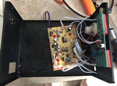
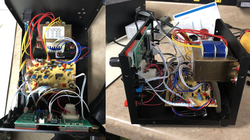
Upon opening the 853D up, [EEpromChip] realized the internal layout wasn’t terribly efficient. There was plenty of extra room inside the case to begin with, but if the transformer was removed from the bottom of the case and mounted to the rear it would really cut down the device’s footprint.
After making sure he documented where everything connected, he took all the electronics out of the sheet metal case and cut it down to size on a bandsaw. He then reinstalled circuit boards, and this time mounted the beefy transformer so it hangs over the board rather than sits next to it. The end result is a version of the Kendal 853D which is several inches shorter than before with no impact on functionality.
Turning closets small spaces into dens of Hackerdom has been a topic we’ve discussed previously. Saving every inch is important if you ever hope to move into a grain silo or CNC’d plywood house.


I nominate your first paragraph for a Pulitzer Prize.
“Anyone who’s ever tried setting up a workbench in a tight space knows the struggle: you want to have all your test equipment and tools out and within arm’s reach, but you just don’t have enough surface area. ”
Tardis workbench.
From the link:
“Sorry, I don’t have bananas in my lab.”
(He’s talking about measurements)
B^)
Yo dawg, we heard you like reworking stuff, so we’ve done some reworking stuff on your reworking stuff.
B^)
Came for this comment. I was not disappointed.
But what if you could replace the internal powersupply with an external one, and mount that under your desk? and also mount the pcb vertically to the backplate of the case, wouldn’t that save even more space?
That is a topic I have been going on a personal vendetta against in my house:
External power supplies.
All of the common gear (like router/wifi/phone) is getting mounted with nicer corded power supplies to remove wall-warts. (50% done).
Everything with a fixed cord is getting a removable cord (3 more to go).
And everything with an external power supply is getting condensed to have less cord to the power supply, and a longer supply cord to try and standardize my cables and spares.
Most of my small stuff on wall-warts is either 5 or 12v, so I am actually looking at replacing a bunch of things with that neat “programmable” Qualcomm quick charge 3.0 adapter trick.
What’s
> that neat “programmable” Qualcomm quick charge 3.0 adapter trick
?
qc3.0 has adjustable voltage output, but it requires the device to communicate with the charger. He’s talking about tricking the charger into outputting those different voltages without an actual device connected (besides whatever is required to communicate with the charger).
Three words: PoE. Safe, standardised, and easy to make or buy adapter dongles for 12V, 9V, 5V etc. My PoE switch was one of my best buys.
Hey! HackaDay published my work! It’s a great day indeed.
Congrats!
The thing I don’t like about internal supplies is that you can’t run the devices on batteries as easily, there’s more heat inside the case, and if anything happens you can’t easily swap the supply. I’d imagine there’s cost issues in some cases too, designing in a power supply instead of using an already certified one.
The thing I don’t like about wall warts is when they take up 2-3 spots on a surge protector. But that’s easily solved by including adapters that don’t do that crap, or by using USB since almost all phone chargers are pretty small.
I think I’d love to see USB-C get mass produced to where it could power everything from routers to hot glue guns to cordless drill chargers.
My first ‘mod’ to mine was a longer power cable. Which ironically, I’ve since installed closer power points at my work bench.
The next mod is to fit a proper power switch – the transformer hums quite noticeably.
I wonder if a SMPS would work well in these things? Could shrink the unit even more! (Though too small may impact on the hot-air tool’s mount.)
I like the idea, but more analysis would be appreciated (disclaimer: I’m a software guy, salt my comments liberally):
What is the thermal situation in the original case? I’m guessing the transformer gets warm, a thermometer or (better yet) thermal imaging camera to see what the pattern of heat is when this unit is going full-force. Placing the PCB immediately above the transformer means all the heat goes right to the board. Plus a smaller enclosure means less air flow, generally. Sure doesn’t seem to have any active cooling.
Similarly, the transformer’s got RF characteristics and placing it closer to the digital circuits sure seems a recipe for interference. The enclosure (of any size) should be sufficient to keep the RF inside, yes? (Relevant to discussions above about externalizing the power supply.) How about some characterization of the transformer’s RF output?
I had wondered about the RF introduction to the circuitry. Not sure how much effect it has on the board. Of course, you are talking to a guy who took his case to a bandsaw.
Less than a switching psu