Deep in the heart of your latest project lies a little silicon brain. Much like the brain inside your own bone-plated noggin, your microcontroller needs protection from the outside world from time to time. When it comes to isolating your microcontroller’s sensitive little pins from high voltages, ground loops, or general noise, nothing beats an optocoupler. And while simple on-off control of a device through an optocoupler can be as simple as hooking up an LED, they are not perfect digital devices.
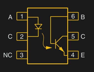 But first a step back. What is an optocoupler anyway? The prototype is an LED and a light-sensitive transistor stuck together in a lightproof case. But there are many choices for the receiver side: photodiodes, BJT phototransistors, MOSFETs, photo-triacs, photo-Darlingtons, and more.
So while implementation details vary, the crux is that your microcontroller turns on an LED, and it’s the light from that LED that activates the other side of the circuit. The only connection between the LED side and the transistor side is non-electrical — light across a small gap — and that provides the rock-solid, one-way isolation.
Music, Motors, and High Voltages
I was just building a MIDI-compatible device, and because MIDI connects musical instruments together over a distance, there’s the possibility for a ground loop that could make an audible hum in everything that’s plugged together. But my little microcontroller needs to speak 31,250 baud serial to the other microcontrollers in the synthesizers. How can they do this without a common ground? All devices with a MIDI-in port send the voltage over the wires straight into an optocoupler.
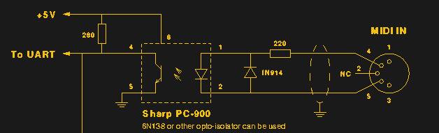
Imagine that my microcontroller is on the right side of this circuit, plugged into the synthesizer’s MIDI-in port. It signals the synth by sending up to 5 mA down the cable, lighting up the LED inside the opto, and pulling down the “To UART” line on the left side. There’s no common ground to hum at 50 Hz (here), but the serial data gets through: current signal → LED → (created light) → phototransistor → current signal → isolated device.
Just as important, an optocoupler can protect the rest of the world from your microcontroller if it’s running at an odd voltage. For instance, a project that uses a transformerless power supply should be isolated because what the microcontroller sees as “ground” may be up to a few hundred volts off from earth ground. Any input to the microcontroller or output from the microcontroller will need to pass through the LED side of an opto to keep you from getting shocked.
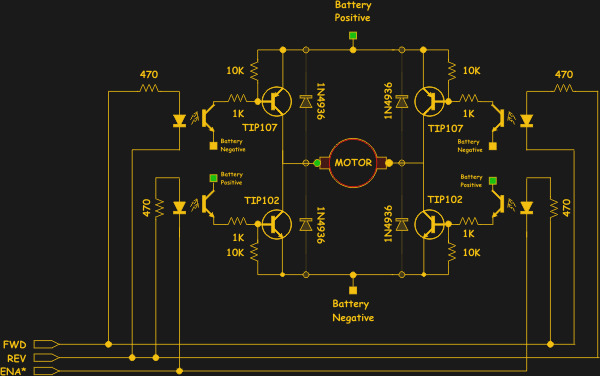
A final example of a good use for optocouplers is connecting logic circuits up to beefy motors with an H-bridge circuit. First, the motors may require a voltage that would fry your microcontroller, so you’ll usually need at least a transistor between the micro and the motor-driving transistors. But especially with stepper motors or DC motors driven with PWM signals, the motors’ power rails can be a very noisy place. And with large currents ebbing and flowing, not even the ground wires are safe.
Using optocouplers in a motor driver design kills two birds with one stone. Not only can you interface the low-voltage microcontroller with the higher voltages needed to turn off the high-side transistors in this example, but there’s absolutely no way for all of the voltage noise in the bridge circuit to disrupt the microcontroller. You’re free to use the ADCs on your little robot, safe from motor noise!
In all of these examples, notice that the optocoupler works one way only. Signals can only pass from the LED side to the transistor side. So if you want to couple something like an SPI or UART signal, you can. But if you want to isolate I2C, because signals need to go in both directions, you need to buy an I2C switch to disentangle the signals.
Circuit Characteristics and CTR
The main selling point of an optocoupler is the isolation between the two sides. A 4N25 optocoupler boasts an isolation test voltage of 5,000 V between the LED and transistor. If you put 500 V across it, you would see an effective resistance of more than 1012 Ω. For all normal-voltage purposes, an optocoupler keeps the hot side hot and the cold side cold.
So what do you need to know before using an optocoupler in your circuit? The sending side turns on an LED, so you’ll just need to know its threshold voltage and how much current it can take. The circuitry for the receive side is more involved, because it can be a photodiode, which will probably need an op-amp buffering circuit, or a phototransistor, which can sometimes get along without.
To figure out what kind of conditioning circuit is required, there’s one more missing ingredient: the amount of light the LED puts out per milliamp of input current (the efficiency of the LED), and the number of milliamps of output current the transistor or diode will pass per photon of light that hits it (the gain of the photo-device). Cancelling out the light in the middle, you get the current transfer ratio (CTR), the current through the collector of the transistor divided by the current put through the LED.
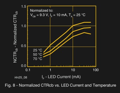
CTRs vary from 1/100 for photodiode-based optocouplers to around 1/2 for phototransistors and up to 5-ish for photodarlingtons. The tradeoff for this gain, all the way up the chain, is in speed of response. You probably shouldn’t be sweating the CTR very much anyway, because you’ll likely be driving another transistor or feeding a microcontroller’s high impedance input with the opto’s output.
CTR varies by a factor of two across the LED’s drive current, and even with temperature and across different parts. In short, CTR is useful for ballparking, but it’s not a hard design spec. The bottom line is that you’re definitely going to need an external amplifier, usually in the form of an op-amp, with a photodiode, and you might be able to get away with a single transistor amp for the transistor types.
For an optocoupler with a Darlington output, you may not even need any other active components. The simplest circuit consists of a resistor to limit the current from the power supply into the transistor. If you know that the LED is driven with 5 mA, for instance, and the CTR is 1, then the transistor should also be able to pull 5 mA to ground, so if you pick your load resistor to pass less than 5 mA, the output should swing nearly rail-to-rail. Since CTR is a fuzzy parameter, you might want to design around 2 mA or so in this example.
Finally, you’ll also often see a reversed diode (as in the MIDI spec) in parallel to the LED. This is to prevent reversed or AC currents from blowing the LED out. Some of these IR LEDs burn up with as little as two or three volts applied in reverse, so an external diode is cheap insurance for a penny.
The Need for Speed
Besides an abstract appreciation for optocouplers, my main reason for writing this article is a circuit of Bob Pease’s that turns a mediocre jellybean optoisolator into a high-speed powerhouse. As I mentioned briefly above, I was implementing MIDI for a synthesizer project. MIDI is basically an agreed-upon set of codes transmitted over an opto-isolated 31,250 baud UART, 8N1.
The MIDI spec calls for shorter than 2 μs rise and fall times when 5 mA is pushed through the LED, and it recommends a Sharp PC-900 or 6N138 (PDF datasheet) for the optocoupler. The 6N138 is a photodiode with a built-in amplifier; it has just enough speed and a CTR > 3. It would be totally convenient. I don’t have one in my parts boxes, so I started looking around for alternatives.
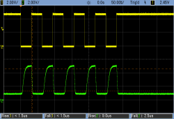
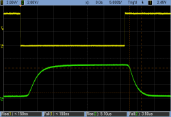
I first started out with a 4N29 Darlington optocoupler because it has a high CTR and I was hoping to get away with just a load resistor, but its rise time is too slow at around 9 μs even when the resistor is fine-tuned. So I took out a 4N25, which is a normal transistor optocoupler, which according to the Vishay part’s datasheet has a typical 2 μs rise time, which is right on the edge, but that’s when it’s driven by a 10 mA current into the LED. In the simple circuit above, I couldn’t get it any faster than 5 μs at 5 mA. Boo!
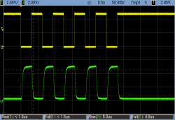
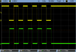
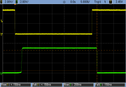
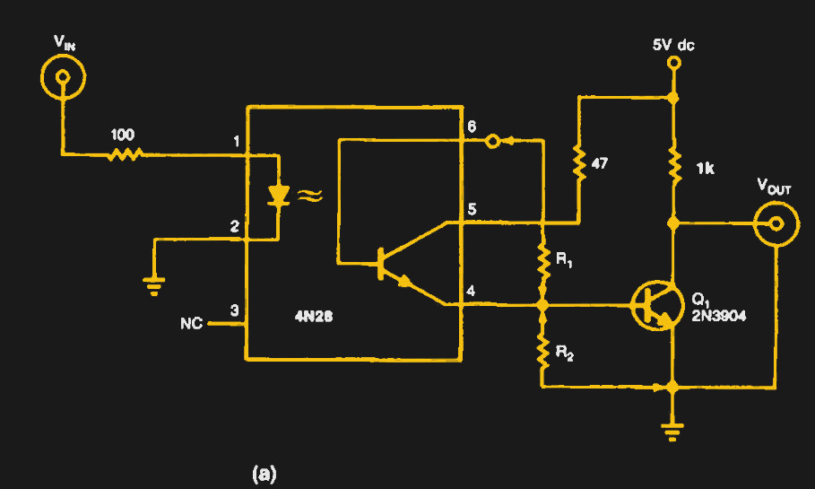 The solution was this circuit from Bob Pease’s excellent Troubleshooting Analog Circuits. This gem reduces the rise and fall times of the 4N25 I had on-hand by a factor of at least 25, from a not-in-spec 5 μs to well under 200 ns. Problem not just solved, but completely obliterated. Beautiful!
The Pease circuit essentially follows the output of the 4N25 with another transistor, increasing the effective CTR of the circuit as a whole, and letting the output voltage swing rail to rail. This is the kind of amplification that you’d need with any but the simplest phototransistor circuits anyway.
But it also adds two resistors. R1 pulls the base of the output transistor down which helps shorten the fall time when the phototransistor is no longer conducting. R2 provides positive feedback to the base of the phototransistor, helping it to snap on faster by adding to the photo-electric base current when the transistor starts to turn on. I used Pease’s suggested values of 2 MΩ for R1 and 1 kΩ for R2.
This circuit is fantastic. If you’re building a MIDI device, and you’re afraid of slow rise times, which you should be, give it a try. With zero tuning, it turns a heap of common components into the equivalent of a much faster optocoupler.
Your Turn
Optocouplers are somewhat of an odd beast. On one hand, they’re entirely intuitive: an LED and a phototransistor. On the other, they can be pushed to performance extremes with the right supporting circuitry. What’s your favorite opto circuit?


Add the extra circuitry, or instead just use a 6N137, with a rise time of 23ns. About the same price, smaller BOM, less board area. https://www.vishay.com/docs/84732/6n137.pdf
You haven’t read full article have you?
Minor nitpick – that is NOT a Darlington pair – Darlingtons have the collectors tied together. Do that in this cicuit and it’d be slow again. Pease was smarter than that.
ref: https://en.wikipedia.org/wiki/Darlington_transistor
Which you’ll note usually doesn’t have the resistor marked R2 here in the circuit either – which when lacking slows things further.
You’re right. Nit-fixed.
I’m using just a 6N138 for my Kerberos MIDI interface, with an additional schmitt trigger buffer and ESD protection diodes. Sold several 100 times. No problems so far:
https://i.imgur.com/pgQTwri.png
MIDI, Kerberos…
in the same…
Is it so the Kerbers can jam on guitars while jammed in their space capsule?
Sorry, I got confused on Kerbal and Kerberos…
We designed this kit that uses the 6N238: http://a.co/8IkC23R
That’s the part suggested in the MIDI spec, so that should be a good choice.
As many folks have pointed out below, there are faster options available today that would blow the late-80’s tech out of the water.
I didn’t have either in my closet, although I’ve since ordered some 6N138s for the next project, whatever that’s going to be.
My favorite application for optos:
While maybe not technically an “optocoupler”, solid state relays with FET outputs make nearly perfect audio switches with extremely low distortion and low noise coupling – with no added risk of “ground loops”. They can be switched remotely with a current loop that makes the control very noise immune. And since they turn on fairly slowly, clicks and pops are very low.
Hey that sounds pretty interesting, I’ll keep that in mind for future audio projects.
I’ve never actually learned the difference before and now you got me wondering. What makes a solid state relay not an optocoupler, anyway?
A solid state relay is often a triac (or similar), triggered by an opto-device. Many also include zero-crossing detection circuits and various ways to help with triac commutation.
These Fet-output opto’s are also often used in oscilloscope’s to short the AC cap and switch to DC measurement.
Also for the trigger output.
Pretty impressive performance. I like to use the output as a current steering device. This reduces the voltage across the phototransistor during change, it tends to be the capacitance that reduces the performance, and less voltage change means less effect of capacitance. Basically try keep the output voltage swing as low as possible, build your circuit to detect current change, not voltage change.
For analogue they can be very noisy. Perhaps a good source of white noise?
I’m confused by this comment. Are you assuming the layout sucks?
One thing to keep in mind when using optocouplers used for high voltage DC isolation (as in the motor driver example) is that you should always check that the device you’re using is rated for DC use.
While almost any optocoupler is fine for AC or ground loop isolation, many of them will slowly fail if exposed to standing, high-voltage DC potential for months at a time. It has something to do with charge injection into the photo transistor substrate.
There’s usually a note or two in the datasheet, and, for extreme cases, there are devices specifically designed to resist kilovolts of DC forever.
As long the the working voltage does not exceed the rated working voltage of the IC, there is no significant MTTF difference between AC and DC.
The differences in AC vs DC isolation have more to do with PCB layout and the design of the opto’s surrounding circuit.
Holy misinformation, batman. The 4N25 di-electric withstand rating is 2500V, and the rated working voltage is 250V to 400V, depending in the version of the test standard
It’s also worth checking out the IL600 series. They have a completely different operating principle (the giant magnetoresistive effect), and are much faster than typical optocouplers.
Just keep them out of strong magnetic fields. Setting a neodymium magnet on the package will temporarily shut it down.
Analog Devices and TI also make fast digital isolators.
Thank you, that’s exactly what I was looking for but didn’t know they existed
Interesting–have to need the speed, though, as they are around 10x the price of opto devices.
You will also degrade speed by over-driving the input LED. It result in an super saturated transistor which takes longer to turn off. Just because you can drive the LED with 20mA or more doesn’t mean you have to!
Another point – Because it’s an LED, an opto-isolator will suffer from degradation over time as the brightness of the LED degrades. Driving the LED at a lower current lessens the effect over time so the design will last longer. This is especially true if the design nreds to work for extended periods of time at hot temperatures.
True, but. I was experimenting around with these (admittedly slow) optos, and noticed that turn-on speed increases with drive current. This also shows up in the datasheets.
MIDI spec is a 5 mA loop, and I’m connecting to all manner of external devices, so although I _could_ drive the LEDs harder, it’s not guaranteed that any other devices will.
I would not call 31,250 baud high-speed :) just a thought.
“Anything less than 1GHz is DC”
-unknown
And above 1THz is witchcraft
B^)
So where do you buy your AC scopes? ;-)
Fair enough! But it’s high speed for a part that’s designed for 60/120 Hz.
You wouldn’t call 100 mph fast in a Ferrari, but it’s downright amazing for a Vespa.
s/amaz/terrify/
B^)
This article is ripe to use the terms “galvanic isolation” and “galvanically isolated”.
I’ve been happy with an H11L1. Don’t forget to put the cap across the drive resistor.
My favorite is the opto-triac. I often use them in high power AC phase control applications and to force commutation in power triacs to prevent arcing of electromechanical relays.
I’ve got a system with better than 100 kV of isolation: it’s called a cell phone with a probe plugged into its mic jack (through a voltage divider, of course), sending data over WiFi or Bluetooth. Sampling rate >40kHz.
This can also be done with microcontrollers, of course. Point is, optoisolators are a child of the 1970s. There are better ways today.
Like what?
Magnetic isolators do pretty much the same thing but better.
Jesus, he was just doing MIDI and got a high tension GHz bashing.
Get a grip.
Hang on. This explanation doesn’t make much sense.
“R2 provides positive feedback to the base of the phototransistor, helping it to snap on faster by adding to the photo-electric base current when the transistor starts to turn on.”
First, R2 doesn’t connect to the optocoupler base except through 2 Mohm R1. The time constant there is going to be a few microseconds, generously assuming the base to be less than a few pF.
Second, the base of Q1 (and therefore R2) can’t swing more than 0.7V above ground.
Third, R2 is always more negative than the base of the phototransistor: there’s no way it can add current to the base of the phototransistor.
Pease, Himself, doesn’t describe the circuit that way: he claims it gets it to only 5 us, not 200 ns, and He abbreviates the explanation, saying R1 is to “tailor the bias”.
My guess is that R1 just biases that phototransistor further off, and removes photo-generated charge faster when the light stops, rather than waiting for charge to dribble away through the base.
My guess is that R1 and R2 labels need to be switched.
I tried the schematic myself and I also did a LTspice simulation and it seems like either I miss something, or it doesn’t work:
https://cdn.hackaday.io/images/4024401526020026370.d75a6638d144cc3f7e9b167b32c2350a
It seems to me like he is trying to bias an NPN transistor (the one inside the opto) with the emitter.
I automatically thought of my project and tried to see if I can improve the slopes of my mosfet and then tried with a bipolar transistor and then with multiple optocouplers and transistors, different values, voltages and resistors. The effect it’s the same and I don’t know where Elliot Williams took the schematic from. Any additional info, Elliot?
I’ll keep trying maybe to switch the resistors between themselves. Here is my project page:
https://hackaday.io/project/94905-hakko-revenge
Oh, yes. I ran the simulation again. It seems to be working only if you put that 1K resistor into the collector of Q1. I can see why. That does not help me very much and I cannot implement this in my schematic.
There is a very similar but slightly more simple (elegant?) circuit in the book ‘More Advanced MIDI Projects’ by R. A. Penfold published by Bernard Babini in 1989 (if you can find it). It uses a BC549 switching transistor at the output to increase a relatively inexpensive TIL111’s switching speed and does away with two of the resistors. The book has plenty of other practical MIDI hardware circuits to investigate…
An opto I was using loaded the circuit too much, and I was pressed for time. Used a FET to switch the higher voltage instead… and ended up blowing up an expensive piece of kit.
I knew better, ignored it and am paying the price. Always use an opto to switch higher voltages!
I remember doing something similar when I was about 15 trying to make a light chaser using an electronic dice kit to drive triacs. Using one Chanel was fine but when I added a few more triacs directly connected to the counter chip a large hole suddenly appeared. ( thankfully I knew enough about mains voltage not to touch anything when it was plugged in)
Check out digital isolators. Fast rise times, high isolation, packages with same pin outs as optos. No external components required.
agreed, the CMTI figures are much better too.
It’s a small jump from optocouplers to fibre-optic cables.
I’ve been told it’s technically possible to use the same fibre in duplex (for your I2C condition) by using different wavelengths, but when you factor in the cost of a 2nd fibre it’s rarely considered practical.
sounds like a good article..
Can you change the schematic image so that it magnifies when you click on it?
Here’s a MIDI Breakout Board Kit we designed which uses a 6N138 Opto http://a.co/8IkC23R
Schematic and sample Arduino code here: https://github.com/ubldit/MIDI_BreakoutBoard
Happy tinkering!
There are also ‘logic output’ optoisolators for high-speed, digital applications. The TLP105, for example, claims 75ns max for rise and fall times. But they’re cost you a pretty penny.
*they’ll, or “they’re gonna,” or “they’re trained to,” or “they’re not humans, and thus would feel no guilt to”
Nice trick with the 4N25, but the schematic is near inscrutable, especially what’s happening around R1 and R2. Would it be possible to get a better image in the article, or a link to the original?
Fixed. Click on the image to see the full-res version.
It would be interesting to see physical teardowns of different kinds of opto- / magneto- / etc isolators.
Is it possible to extract say the phototransistors or photodiodes? how do they compare to easily sourced discrete photodiodes? I can imagine them being faster than usual BPW34, if they are smaller and hence have less capacitance?
Same for the giant magnetoresistive based isolators: while we all knew HDD heads contained them, these would be a more reliable, cheap, repeatable source since you don’t need to scavenge them from HDD heads…
I have a small nit pick of the statement: “..and that provides the rock-solid, one-way isolation.” ISOLATION is “all ways” not just one way. Diode isolation is one way, ignoring their reverse current. The other thing to say about HV isolation is that failure modes are typically catastrophic, maybe even more so than ESD zaps on an IC (e.g. “lightning bolts”). I worked for a company that sold navaids to the FAA, and you should have seen some of the stuff we got back that got hit my lightning, even through huge solid copper bus bars and layers of lightning protection. Trouble was, these were from VOR equipment located on top of mountains and the only good lightning target was their metal shelter and its contents.
PCB layout is also critical to the success of any overall isolation scheme, and may even require something like a tiny Faraday shield. I recently got some HV stuff from China and noticed PCB material removed between a relay’s HV and LV terminals in order to affect better isolation (assuming low humidity).
IR remotes and their receivers have good isolation. IrDA can do >1 Gbps — check Wikipedia. Full duplex complicates designs.
My favorite opto circuits are home made vactrols I make to build audio fx (compressors etc). One led here, one photoresistor there, black tubing around and voila: a resistor that can be driven by everything, from the same signal rectified and amplified to a microcontroller pin. Make two and connect the two leds in series with their center connection wired to a push-pull capable output, then wire the two photoresistors in series and you get a potentiometer you can drive using pwm. Photoresistor also are inherently slow, so unless one uses a frequency in the audio range, there’s no need for filtering as the driving signal will never bleed into the audio path.
If you end up here trying to get a 4pin optocoupler like the l817, ltv817 or pc817 working for MIDI data transfer you need to use the following amplifier layout https://www.mikrocontroller.net/attachment/296701/PC8x7-MIDI.png as found on this german forum https://www.mikrocontroller.net/topic/400055
Without this the output will look like a bunch of shark fins with an 8k pull up and like a single blob with a 220ohm pull up (as per the fastest response time on the ltv-817 datasheet!)
Bob Peases original publication of this circuit has NO load resistor in the output transistor’s collector.
Obviously an error, but whose error ? I doubt it was Bob’s.
Hello. Thank you for the schematic, but there’s a smal error or misinterpretation possible in the schematic. Usually all ground symbols are tied to the same point. If you do that in this schematic, you loose the isolation and create a ground loop. Pin two of the optocoupler should be tied to pin 5 at the back of the midi in plug ONLY, and not to the rest of the schematic ground. The reverse protection diode at the input is also missing.