Vector Network Analyzer Uses SoC FPGA

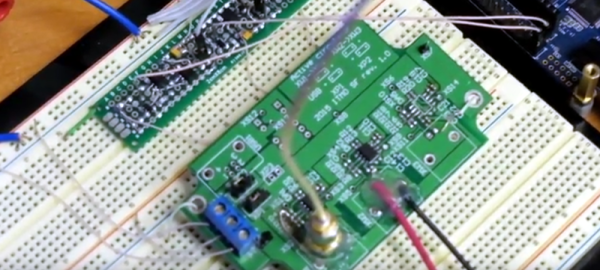
If you are working with AC circuits a vector network analyzer (VNA) is quite handy. As an entry to the InnovateFPGA competition for students, [Evgenii Vostrikov], [Danila Nikiforovskii], and [Daniil Smirnov] created a VNA using a DE10-Nano, high-speed analog to digital and digital to analog converters, and a circulator. Most of the details are in the video below, and on the project’s GitHub page.

The DE10-Nano has a dual-core ARM processor and an Altera FPGA in one package. That allows you to use the CPUs where that makes sense and still leverage the FPGA where you need high performance.

The circulator uses an op-amp to allow the test signal to route to the device under test, while steering any reflected signal back to the device for measurement. The design also uses a lock-in amplifier, something we’ve talked about a few times recently. This allows less expensive converters to generate magnitude and phase information.

Judging by the fan in the video, we suspect the setup gets a little toasty. The GitHub page has a lot of Russian on it, so we aren’t sure how much we could puzzle out since our Russian skills were mostly from watching the Adventures of Moose and Squirrel.

If you are interested in a VNA, they aren’t as expensive as they used to be. Particularly, if you roll your own and already have some things in your junk box.

Continue reading “Vector Network Analyzer Uses SoC FPGA”

Pic16maze secret maze game

PIC16Maze Upgrades Secret Maze Game

We really like it when a reader is inspired by something they see on Hackaday, build on it, and let us know so we can pass it on. In this case, [Vegipete] made a secret maze game using a minimal number of parts and some neat software trickery.

It’s built around an 8-pin PIC16F18313 microcontroller, uses a joystick for input, and nine WS2812 LEDs to display the player and the surrounding maze walls. His inspiration was [David Johnson-Davies’] minimalist secret maze game built around the 8-pin ATTiny85. In that one, [David] cleverly used charlieplexing to get four pins to control four LEDs and four pushbuttons. [Vegipete’s] use of the WS2812 LEDs allowed him to control the LEDs with just one pin, and also get color while using three pins for the joystick and its button. He may use another pin in the future for sound and vibration.

He goes into some detail on the WS2812 protocol, how communication is done with the LEDs using just one pin and different pulse-lengths to represent 0 and 1. We’ll leave you to see his post for more depth but basically, he introduces a module on the PIC called the Configurable Logic Cell (CLC) which makes this easy and frees up processor cycles for the user’s code to do other things.

Secret maze wall bits
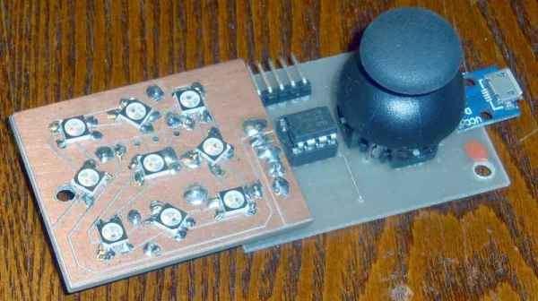
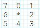
His source code is available on request but he does detail a neat software trick he uses for rotating the view. It may be confusing for some but as you move through the maze, your viewpoint rotates so that up is always the direction you’re facing. Luckily, the walls surrounding the user can be represented using 8-bits, four for east, west, north, and south, and four more for the corners. The maze is stored as a bitmap and from it, 8-bit values are extracted for the current position, each bit representing a wall around the position. To rotate the walls to match the user’s current orientation, the bits are simply shifted as needed. Then they’re shifted out to set each LED. Check it out in the video below.

It works very well despite the minimal interface and part count.

Continue reading “PIC16Maze Upgrades Secret Maze Game”

Diagram generated by QElectroTech

QElectroTech: An Open Source Wiring Diagram Tool

There’s a few open source options out there for creating electrical schematics. KiCad and Fritzing are two that will take you from schematic capture to PCB layout. However, there’s been limited options for creating wiring diagrams. Often these are created in Microsoft’s Visio, which is neither open source nor well suited for the task.

QElectroTech is an open source tool for drawing these types of diagrams. It consists of two tools: an element editor for creating schematic symbols and a diagram editor for creating your drawings. Libraries of common symbols are also included, along with the IEC 60617 standardized symbols.

Being a schematic editor, QElectroTech does a good job of drawing clean connections between components. Connections are automatically routed at 90 degree angles and are easy to drag around. Systems made up of more than just electrical connections are also a good fit for the software. Here you can see piping and manual valves as well as electronic sensors and actuators all in the same diagram.

Next time you need to document the wiring of something, QElectroTech is a good option to try. It’s been around since 2008 it is under active development, and there are Windows, OSX and Linux version (including a PPA for nightly builds) available.

Breadboarding: Git For A/B Testing Actual Bread

We will be the first to admit, we like to use Git for a lot of things that are probably off the beaten path. But now thanks to [hendricius] you can find out how to make your own bread on GitHub. Let’s get one thing straight. This isn’t the breadmaker fad from a while back, although we are surprised we don’t see more hacked together breadmakers with Internet connectivity. This is old-fashioned bread baking with a bowl, some ingredients, and an oven or another heat source.

You might think this is just using Git as a repository for recipes, but it is more than that. According to [hendricius]:

Learn how to master the art of baking the programmer way. If you love programming, you will also enjoy breaking some bread. A/B test, iterate and ultimately become a self-taught baker. This repository is dedicated to becoming your bread manifesto with useful tricks and hacks. Furthermore, the goal is to illustrate how easy making bread is and that you can get started today without expensive tools.

Continue reading “Breadboarding: Git For A/B Testing Actual Bread”

The Metabolizer Turns Trash Into Treasure

The amount of stuff we humans throw away is too damn high, and a bunch of it harms the ecosystem. But what are you gonna do? [Sam Smith] thinks we can do better than shoving most of it in a landfill and waiting for it to break down. That’s why he’s building The Metabolizer. It’s a series of systems designed to turn household trash (including plastic!) into useful things like fuel, building materials, and 3D prints.

The idea is to mimic the metabolism of a living organism and design something that can break down garbage into both useful stuff and fuel for itself. [Sam] is confident that since humans figured out how to make plastic, we can figure out a system to metabolize it. His proof-of-concept plan is to break down waste into combustible, gaseous fuel and use that fuel to power a small engine. The engine will power an open-source plastic shredder and turn a generator that powers an open-source plastic pellet printer like the SeeMeCNC Part Daddy.

Shredding plastic for use as a biomass requires condensing out the tar and hydrocarbons. This process leaves carbon monoxide and hydrogen syngas, which is perfect for running a Briggs & Stratton from Craigslist that’s been modified to run on gaseous fuel. Condensation is a nasty process that we don’t advise trying unless you know what you’re doing. Be careful, [Sam], because we’re excited to watch this one progress. You can watch it chew up some plastic after the break.

If [Sam] ever runs out of garbage to feed The Metabolizer, maybe he could build a fleet of trash-collecting robots.

Continue reading “The Metabolizer Turns Trash Into Treasure”

Optocouplers: Defending Your Microcontroller, MIDI, And A Hot Tip For Speed

Deep in the heart of your latest project lies a little silicon brain. Much like the brain inside your own bone-plated noggin, your microcontroller needs protection from the outside world from time to time. When it comes to isolating your microcontroller’s sensitive little pins from high voltages, ground loops, or general noise, nothing beats an optocoupler. And while simple on-off control of a device through an optocoupler can be as simple as hooking up an LED, they are not perfect digital devices.

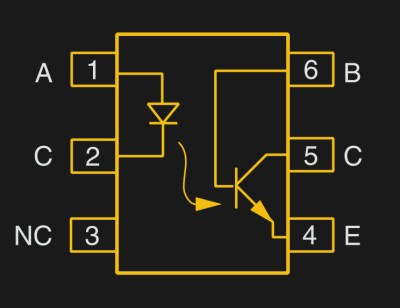
But first a step back. What is an optocoupler anyway? The prototype is an LED and a light-sensitive transistor stuck together in a lightproof case. But there are many choices for the receiver side: photodiodes, BJT phototransistors, MOSFETs, photo-triacs, photo-Darlingtons, and more.

So while implementation details vary, the crux is that your microcontroller turns on an LED, and it’s the light from that LED that activates the other side of the circuit. The only connection between the LED side and the transistor side is non-electrical — light across a small gap — and that provides the rock-solid, one-way isolation.

Continue reading “Optocouplers: Defending Your Microcontroller, MIDI, And A Hot Tip For Speed”

Friday Hack Chat: Open Hardware For Science

Scientific equipment is expensive. It can cost hundreds of thousands of dollars to set up a lab. Simply the cost of machines, like data acquisition units or even a simple load cell, can cost hundreds of dollars. This makes research cost prohibitive, and that’s the case even if you do spend a dozen hours a week writing grant proposals. Citizen science is right out, because the cost of the tools to do science is so high.

For this week’s Hack Chat, we’re going to be talking about Open Hardware for science. This is the chat that’s all about Open Source equipment, hardware modular electronics, and Open designs to make the tools that make science.

Our guest for this week’s Hack Chat is [Dr. Alexxai Kravitz]. He has a PhD in Neuroscience from UPenn and completed a postdoc at the Gladstone Institutes in San Fransisco. [Lex]’s research focuses on understanding the reward circuitry in the brain, and his publications use a variety of experiments to examine this, including behavioral testing, in vivo electrophysiology, and optogenetics.

For this Hack Chat, we’re going to about how Open Source has made more science possible. Of note, we’ll be discussing:

  • What Open Source science equipment is being used today
  • The initiatives behind Open Source Hardware for science applications
  • Scientific application that could benefit from Open Hardware

You are, of course, encouraged to add your own questions to the discussion. You can do that by leaving a comment on the Hack Chat Event Page and we’ll put that in the queue for the Hack Chat discussion.join-hack-chat

Our Hack Chats are live community events on the Hackaday.io Hack Chat group messaging. This week is just like any other, and we’ll be gathering ’round our video terminals at noon, Pacific, on Friday, May 11th.  Here’s a clock counting down the time until the Hack Chat starts.

Click that speech bubble to the right, and you’ll be taken directly to the Hack Chat group on Hackaday.io.

You don’t have to wait until Friday; join whenever you want and you can see what the community is talking about.