Photoresistors Provide Air Gap Data Transfer, Slowly

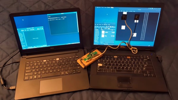
One of the simplest ways of keeping a computer system secure is by using an air gap — that is, never actually connecting the system to the network. This can often include other peripherals like USB drives and other removable storage as well, so getting information to and from secure (or compromised) systems behind air gaps can often present a challenge. But assuming you have local access to the computer and your parts bin handy, these optical solutions from [Nikolay] can allow  data transfer to or from such off-line computers.

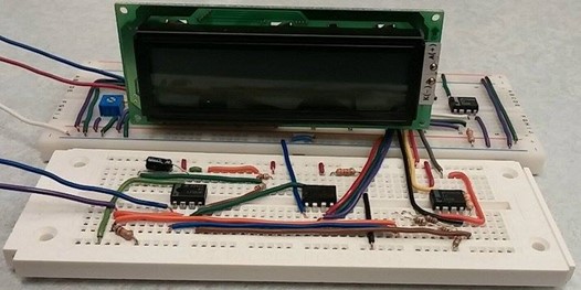
[Nikolay]’s specific use case for this project is to transfer small amounts of information to or from computers that may be compromised in some way, or computers that might otherwise be dangerous to connect to other equipment. There’s actually several methods described in the project, the first involves temporarily attaching a photoresistor to the computer’s screen which has been wired into the remains of a USB keyboard. A script running on the compromised machine translates data into a series of white and black squares. The sensors can detect these patterns much like playing Duck Hunt on an old CRT television and transmit the data across the air gap with reasonable certainty nothing harmful crossed with it.

Continue reading “Photoresistors Provide Air Gap Data Transfer, Slowly”

Optocouplers: Defending Your Microcontroller, MIDI, And A Hot Tip For Speed

Deep in the heart of your latest project lies a little silicon brain. Much like the brain inside your own bone-plated noggin, your microcontroller needs protection from the outside world from time to time. When it comes to isolating your microcontroller’s sensitive little pins from high voltages, ground loops, or general noise, nothing beats an optocoupler. And while simple on-off control of a device through an optocoupler can be as simple as hooking up an LED, they are not perfect digital devices.

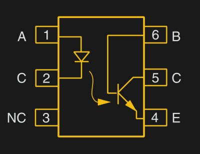
But first a step back. What is an optocoupler anyway? The prototype is an LED and a light-sensitive transistor stuck together in a lightproof case. But there are many choices for the receiver side: photodiodes, BJT phototransistors, MOSFETs, photo-triacs, photo-Darlingtons, and more.

So while implementation details vary, the crux is that your microcontroller turns on an LED, and it’s the light from that LED that activates the other side of the circuit. The only connection between the LED side and the transistor side is non-electrical — light across a small gap — and that provides the rock-solid, one-way isolation.

Continue reading “Optocouplers: Defending Your Microcontroller, MIDI, And A Hot Tip For Speed”

EPROM Timer

[glitch] had a cheap EPROM eraser with very few features. Actually, that might be giving it too much credit: it’s barely more than a UV light that turns on when it’s plugged in and turns off when it’s plugged out unplugged. Of course it would be nice to implement some safety features, so he decided he’d hook it up to a software-controlled power outlet.

Of course, controlling a relay that’s wired to mains is old hat around here, and in fact, we’ve covered [glitch]’s optoisolated mains switch already. He’s gone a little beyond the normal mains relay project with this one, though. Rather than use a microcontroller to run the relay, [glitch] wrote a simple Ruby script on his computer to turn the EPROM eraser on for the precise amount of time that is required to erase the memory.The Ruby script drives the relay control directly over a USB to serial adapter’s RTS handshake pin.

[glitch]’s hack reminds us that if you just need a quick couple bits of slow output, a USB-serial converter might be just the ticket. You could imagine driving everything from standard lamps to your 3D printer’s bed heater (provided you use similar hardware), but it’s especially helpful for [glitch] who claims to forget to turn off the eraser when it’s done its job, which leaves a potentially dangerous UV source just lying about. It’s always a good idea to add safety features to a dangerous piece of equipment!

Body Fat Measurement

DIY Electrical Body Fat Analyzer

Whether you are trying to drop some fat or build some muscle, it’s important to track progress. It’s easy enough to track your weight, but weight doesn’t tell the whole story. You might be burning fat but also building muscle, which can make it appear as though you aren’t losing weight at all. A more useful number is body fat percentage. Students from Cornell have developed their own version of an electrical body fat analyzer to help track body fat percentage.

Fat free body mass contains mostly water, whereas fat contains very little water. This means that if you were to pass an electrical current through a body, the overall bioelectrical impedance will vary depending on how much fat or water there is. This isn’t a perfect system, but it can give a rough approximation in a relatively easy way.

The students’ system places an electrode on one hand and another on the opposite foot. This provides the longest electrical path possible in the human body to allow for the most accurate measurement possible. An ATMega1284P is used to generate a 50kHz square wave signal. This signal is opto-isolated for user safety. Another stage of the circuit then uses this source signal to generate a 10ua current source at 50kHz. This is passed through a human body and fed back to the microcontroller for analysis.

The voltage reading is sent to a MATLAB script via serial. The user must also enter in their weight and age. The MATLAB script uses these numbers combined with the voltage reading to estimate the body fat percentage. In order to calibrate the system, the students measured the body fat of 12 of their peers using body fat calipers. They admit that their sample size is too small. All of the sample subjects are about 21 years old and have a similar body fat percentage. This means that their system is currently very accurate for people in this range, but likely less accurate for anyone else. Continue reading “DIY Electrical Body Fat Analyzer”

Atomic Pinball Clock

[Mark Gibson] sent us a load of details on his build, a WWVB atomic clock using a pinball machine marquee (PDF). This is the upright portion of an old machine that used electromechanical displays instead of digital electronics. It’s big, noisy, and seeing it running might make you a bit giddy. Luckily he included video that shows it working on both the outside and the inside.

It took a bit of probing to discover the connections for relays that control the display. From there he used optoisolation to drive them with an Arduino. With this hurdle behind him, [Mark] set out to add atomic clock accuracy. He picked up a WWVB module and added it to the mix.

Check out his build log in PDF form linked above. He went out of his way to explain how the original parts work, and the processes he used during prototyping. For more of those juicy details we’ve added a photo gallery and his video after the break.

Didn’t get enough pinball goodness from this project? Check out the this digital gas plasma display pulled and reused from a much more modern pinball machine. Oh, and there’s always Bill Paxton Pinball.

Continue reading “Atomic Pinball Clock”