A Low-Cost Current Probe For IoT Applications

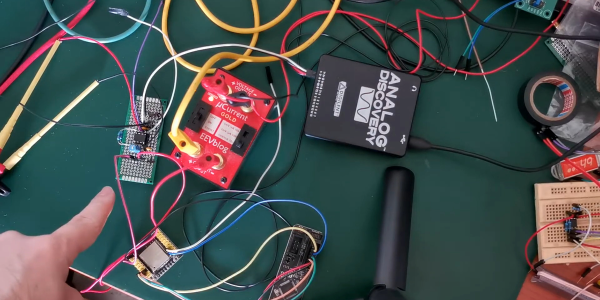
When it comes to the Internet of Things, many devices run off batteries, solar power, or other limited sources of electricity. This means that low power consumption is key to success. However, often these circuits draw relatively small currents that are difficult to measure, with plenty of transient current draw from their RF circuits. To effectively measure these low current draws, [Refik Hadzialic] built a cheap but accurate current probe.

The probe consists of a low value resistor of just 0.1 Ω, acting as a current shunt in series with the desired load. By measuring the voltage drop across this known resistor, it’s possible to calculate the current draw of the circuit.

However, the voltage drop is incredibly small for low current draws, so some amplification is needed. [Refik] does a great job of explaining his selection process, going deep into the maths involved to get the gain and part choice just right. The INA128P instrumentation amplifier from Texas Instruments was chosen, thanks to its good Common Mode Rejection Ratio (CMRR) and gain bandwidth.

The final circuit performs well, competing admirably with the popular uCurrent Gold measurement tool. While less feature-packed, [Refik]’s circuit appears to perform better in the noise stakes, likely due to the great CMRR rating of the TI part. It’s a great example of how the DIY approach can net solid results over and above simply buying something off the shelf.

Current sensing is a key skill to have in your toolbox, and can even help solve laundry disputes. Video after the break.

Continue reading “A Low-Cost Current Probe For IoT Applications”

A Baby Named DJ

Some of us are guilty of picking up questionable hardware from garage sales, fleamarkets, and well-meaning relatives. There is a balance between turning down a good investment and hoarding, and if we figure out how to tell the difference you will be the first to know. [Clem Mayer] may start on the side of unwise acquisition, but he pushes a broken fetal detector into the realm of awesome by converting it to an analog synthesizer, born to headline at an Eastern European dance party.

He starts with a basic teardown, and we get to see how old hardware was serviceable with only two standard screws. It is a good thing too, because the nickel-cadmium batteries are older than some of you and they are in need of replacement. New nickel-metal hydride batteries got it up and running but [Clem] does not have a baby bump so its functionality turned to Pink Floyd era synthesizer circuit bending. Circuit bending involves modifying a circuit for sound it was not intended to make.

Continue reading “A Baby Named DJ”

Optocouplers: Defending Your Microcontroller, MIDI, And A Hot Tip For Speed

Deep in the heart of your latest project lies a little silicon brain. Much like the brain inside your own bone-plated noggin, your microcontroller needs protection from the outside world from time to time. When it comes to isolating your microcontroller’s sensitive little pins from high voltages, ground loops, or general noise, nothing beats an optocoupler. And while simple on-off control of a device through an optocoupler can be as simple as hooking up an LED, they are not perfect digital devices.

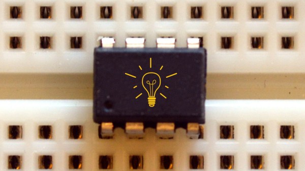
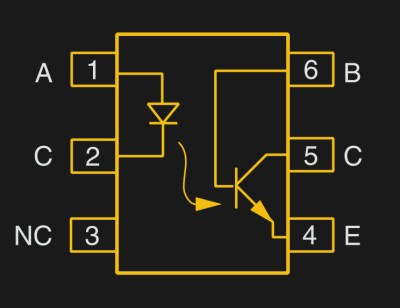
But first a step back. What is an optocoupler anyway? The prototype is an LED and a light-sensitive transistor stuck together in a lightproof case. But there are many choices for the receiver side: photodiodes, BJT phototransistors, MOSFETs, photo-triacs, photo-Darlingtons, and more.

So while implementation details vary, the crux is that your microcontroller turns on an LED, and it’s the light from that LED that activates the other side of the circuit. The only connection between the LED side and the transistor side is non-electrical — light across a small gap — and that provides the rock-solid, one-way isolation.

Continue reading “Optocouplers: Defending Your Microcontroller, MIDI, And A Hot Tip For Speed”

A Mini Op-Amp Based Line Following Robot

LineRobot

There’s no denying it. Super small robots are just cool. [Pinomelean] has posted an Instructable on how to create a mini line following robot using only analog circuitry. This would make a great demo project to show your friends and family what you’ve been up to.

Analog circuitry can be used instead of a microcontroller for many different applications, and this is one of them. The circuit consists of two op-amps that amplify the output of two phototransistors, which control each motor. This circuit is super simple yet very effective. The mechanical system is also quite cool and well thought out. To keep things simple, the motors drive the wheel treads, rather than directly through an axle. After the build was completed, the device needed to be calibrated by turning potentiometers that control the gain of each op-amp. Once everything is balanced, the robot runs great! See it in action after the break.

While not the smallest line follower we have seen, this robot is quite easy to reproduce. What little robots have you build lately? Send us a tip and let us know!

[via Embedded Lab]

Continue reading “A Mini Op-Amp Based Line Following Robot”