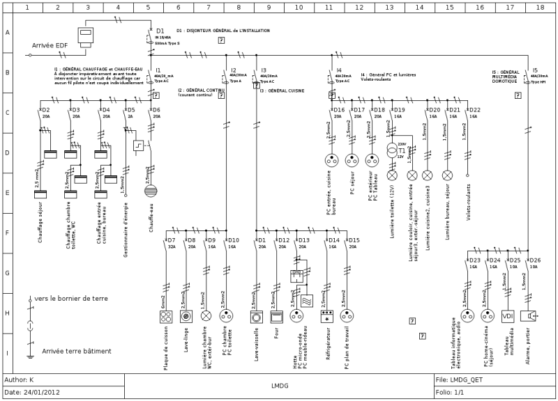
There’s a few open source options out there for creating electrical schematics. KiCad and Fritzing are two that will take you from schematic capture to PCB layout. However, there’s been limited options for creating wiring diagrams. Often these are created in Microsoft’s Visio, which is neither open source nor well suited for the task.
 QElectroTech is an open source tool for drawing these types of diagrams. It consists of two tools: an element editor for creating schematic symbols and a diagram editor for creating your drawings. Libraries of common symbols are also included, along with the IEC 60617 standardized symbols.
Being a schematic editor, QElectroTech does a good job of drawing clean connections between components. Connections are automatically routed at 90 degree angles and are easy to drag around. Systems made up of more than just electrical connections are also a good fit for the software. Here you can see piping and manual valves as well as electronic sensors and actuators all in the same diagram.
Next time you need to document the wiring of something, QElectroTech is a good option to try. It’s been around since 2008 it is under active development, and there are Windows, OSX and Linux version (including a PPA for nightly builds) available.


Why these island solutions?
There are already some programs of this kind. Rather than adding to the list they should bundle their effords.
I think its time that a program could be added to the (open | libre) office suite that is for technical stuff like this. So we have a first goto for technical drawings, maybe for simple 2D engraving, PCB or CNC stuff. Even Windows is getting 3D-Printing tools on board.
https://imgs.xkcd.com/comics/standards.png
Almost every script language
Microsoft is like a 30 year old at a high-school football event…
Everyone knows to avoid their offers — even if free.
Dia works for most people, and does just about everything productive Microsoft removed from their products over the years.
+1 for Dia
I’ve used Dia for everything from network maps and wiring diagrams to general flowcharts
It’s been around for 10 years, so it’s not like it’s new…
“There are already some programs of this kind.” No, not really. Not free at least. Generic diagram editors and 2D CAD SW are usually not prepared to handle multiple sheets and references among them (like relay coils with contactors, and conductors). And their main user base doesn’t need such an added funcionality. I believe (open | libre) office are bloated already without this.
2D engraving – Inkscape
PCB – KiCAD
CNC – LinuxCNC / Fusion360
Different tools for different jobs.
Libre Office is modular and you need not put this in the main package but offer it as an addon,what’s wrong with that?
I tend to use Draftsight – a free, cross-platform AutoCAD clone from Dassault.
It also helps that they provided some symbol libraries last month.
Like the name
I recently used it and loved it. Actually I could not find any other decent open source alternative for electrical schematics (not electronics).
French Wiki, No access to bug tracker without registration, nah.
Yup – ROADBLOCK. Why wasn’t this very obvious limitation reported in the HaD post to begin with? Maybe because there wouldn’t be a HaD post to begin with if this was disclosed? Nah, I don’t wanna believe that… really, I don’t…
Actually the wiki is available in multiple language, including english:
https://qelectrotech.org/wiki_new/en/doc/start
I think it’s very good to address native language for electrotechnical users: unlike programming, peoples in electrotechnical field dont use english much.
The developers read your comment, and the bug tracker is open now.
i have been trying to invent a scripting language for generating wiring diagrams, and i have not had any success thinking of the right idioms. i want to do for wiring diagrams what openscad did for mechanical designs. convenient revision tracking, editing without futzing with a mouse, etc.
uh, that’s all i had to say :)
A more powerful netlist.
I sort of have something as a WIP
Interesting…
I would have never thought to use Visio for electrical wiring diagrams, there are tons of better programs which are just for this application: Eplan, Autocad Electrical, SEE Electrical, …
of course none of these are free as well
I received Visio free (student version back in 2007-2008) but haven’t used it.
I was looking for something fairly basic tonight, something web-based and free but, I had a gander on the Mac App Store and found iCircuit. It’s total overkill for what I want but it has an Arduino simulator inbuilt and you can write code for the Arduino inside the app. Thought that was pretty neat and worth a mention. Also available on Apple App Store, Windows Store and Play Store.
iCircuit – http://icircuitapp.com
Is that Circuit Diagram one a good one though? Looks like all I carnally find. I’m just trying to visualise a 4 position rotary switch and a fan motor that’s all.
https://www.circuit-diagram.org/editor/