Fritzing has been stuck in the mud for just over a year now. There were no updates for many months, and members of the community wondered what was going on. Now, things might be turning around: Fritzing is being rebooted by community members, and there’s a roadmap of upcoming features.
The biggest takeaway from the GitHub discussion is that there simply aren’t enough developers for Fritzing. Fritzing is written in C++ and Qt, and there simply aren’t enough skilled devs to work on it. Future versions of Fritzing will be written in JavaScript.
Other developments in store for Fritzing include clearing out the number of open issues, making a new alpha, generally clean up the entire codebase, and prepare for a release. To that end, there’s also the Freetzing community to rebase the entire project with an emphasis on modularity.
Yes, Fritzing died a terrible death due to legal and funding issues. That still doesn’t mean Fritzing isn’t a valuable tool, though. With these new developments, and entirely new generation of hardware makers can dip their toes into the world of hardware development the easy way, and an entirely new generation of Open Source developers can work on making Fritzing the best tool it can be. There’s never been a better time to get started in Fritzing.
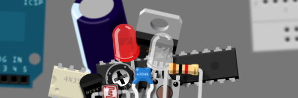
Fritzing is a very nice Open Source design tool for PCBs, electrical sketches, and schematics for designers and artists to move from a prototype to real hardware. Over the years, we’ve seen fantastic projects built with Fritzing. Fritzing has been the subject of books, lectures, and educational courses, and the impact of Fritzing has been huge. Open up a book on electronics from O’Reilly, and you’ll probably see a schematic or drawing created in Fritzing.
However, and there’s always a however, Fritzing is in trouble. The project is giving every appearance of having died. You can’t register on the site, you can’t update parts, the official site lacks HTTPS, the Twitter account has been inactive for 1,200 days, there have been no blog posts for a year, and the last commit to GitHub was on March 13th. There are problems, but there is hope: [Patrick Franken], one of the developers of Fritzing and the president of the PCB firm Aisler which runs the Fritzing Fab, recently gave a talk at FOSDEM concerning the future of Fritzing. (That’s a direct FTP download, so have fun).
If you’re looking to get started in designing a few PCBs, you could use one of the many software packages that allow you to create a PCB quickly, easily, and with a minimum amount of fuss. You could also use Fritzing.
Fritzing is terribad and you shouldn’t use it, but that doesn’t mean you still can’t abuse Fritzing to make it do what you want. [Arduino Enigma] recently posted a tutorial on how to design custom PCB shapes for Fritzing. Yes, Fritzing is no longer limited to rectangular PCBs with sharp corners. You can make PCBs in any shape with Fritzing, provided you spend a few hours futzing about with Inkscape.
The goal for this project was to create a rectangular board without any sharp corners for [Arduino Enigma]’s Sinclair Scientific Calculator Emulator. Fritzing can make a board in the shape of a rectangle, in fact, that’s all it can do, but [Arduino Enigma] wanted a rectangle with radiused corners. After hours of work, we have the writeup on how to do it.
The imported board, with 3mm radiused corners.
The process to create a custom-shaped board, in this case, a rectangle with a 3mm radius on the corners, is simple. First, draw a rectangle of the desired shape, then draw even more rectangles as a sublayer of the current layer. Fritzing requires the layer ID to be named ‘board’, ‘silkscreen’ and ‘silkscreen0’, but this cannot be changed in Inkscape itself — you’ll need to edit the file with a text editor. After creating three layers, each containing the shape you want, simply trim the size of the page to the size of the board. Save the file, edit the file in a text editor, and click save. Launch Fritzing, load an image file, and select the SVG you’ve been working on. In just twenty or thirty quick steps, you too can import any shape you can imagine into Fritzing.
There is one pain point to this process. Editing the layer name manually with a text editor pushes this Fritzing hack from a baroque workaround into something that makes us all question the state of Open Source standards. Unfortunately, this is required because Inkscape does not use layer names as the ID in an SVG file. No, it doesn’t make sense, but that’s just the way it is.
For any other PCB design tool, creating a custom-shaped board is simply a matter of drawing a few lines. Fritzing is different, though. The top copper layer is represented as orange, and the bottom copper layer is yellow, a UI decision that doesn’t make sense, even if you aren’t colorblind. Putting more than two layers of copper on a Fritzing board is impossible. Fritzing is a tool you should avoid for PCB layout. That said, [Arduino Enigma] figured out how to do something in Fritzing that you’re not supposed to be able to do and that’s pretty cool.
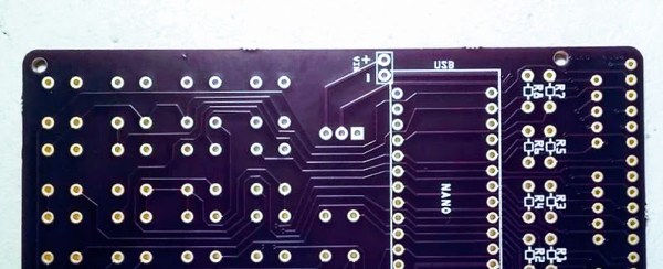
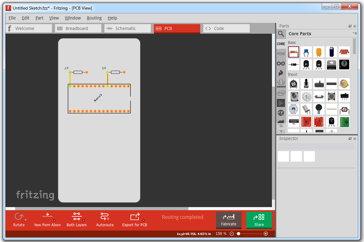
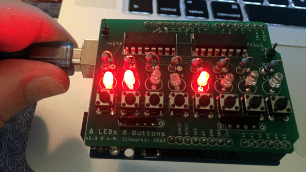
[Allan Schwartz] decided to document his experience using Fritzing to design, fabricate, and test a custom Arduino shield PCB, and his step-by-step documentation makes the workflow very clear. Anyone who is curious or has been looking for an opportunity to get started will find [Allan]’s process useful to follow. The PCB in question has two shift registers, eight LEDs, eight buttons, and fits onto an Arduino; it’s just complex enough to demonstrate useful design features and methods while remaining accessible.
[Allan] starts with a basic breadboard design, draws a schematic, prototypes the circuit, then designs the PCB and orders it online, followed by assembly and testing. [Allan] had previously taught himself to use Eagle and etched his own PCBs via the toner transfer method, but decided to use Fritzing instead this time around and found it helpful and easy to use.
About a year ago we saw Fritzing put through its paces for PCB design, and at the time found that it didn’t impress much from an engineering perspective. Regardless, as a hobbyist [Allan] found real value in using Fritzing for his project from beginning to end; he documented both the process and his observations in order to help others, and that’s wonderful.
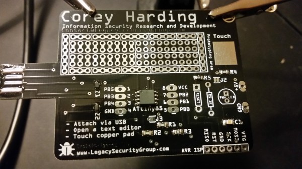
[Corey Harding] designed his business card as a USB-connectable demonstration of his skill. If potential manager inserts the card in a USB drive, open a text editor, then touches the copper pad on the PCB, [Corey]’s contact info pops up in the text box.
In addition to working as a business card, the PCB also works as a Tiny 85 development board, with a prototyping area for adding sensors and other components, and with additional capabilities broken out: you can add an LED, and there’s also room for a 1K resistor, a reset button, or break out the USB’s 5V for other uses. There’s an AVR ISP breakout for reflashing the chip.
Coolly, [Corey] intended for the card to be an Open Source resource for other people to make their own cards, and he’s providing the Fritzing files for the PCB. Fritzing is a great program for beginning and experienced hardware hackers to lay out quick and dirty circuits, make wiring diagrams, and even export PCB designs for fabrication. You can download [Corey]’s files from his GitHub repository.
For another business card project check out this full color business card we published last month.
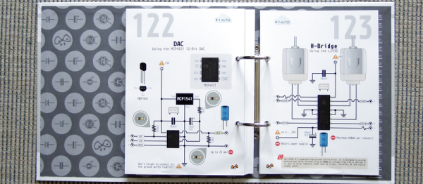
[Alberto Piganti], aka [pighixxx] has been making circuit diagram art for a few years now, and has just come out with a book that’s available on Kickstarter. He sent us a copy to review, and we spent an hour or so with a refreshing beverage and a binder full of beautiful circuit diagrams. It doesn’t get better than that!
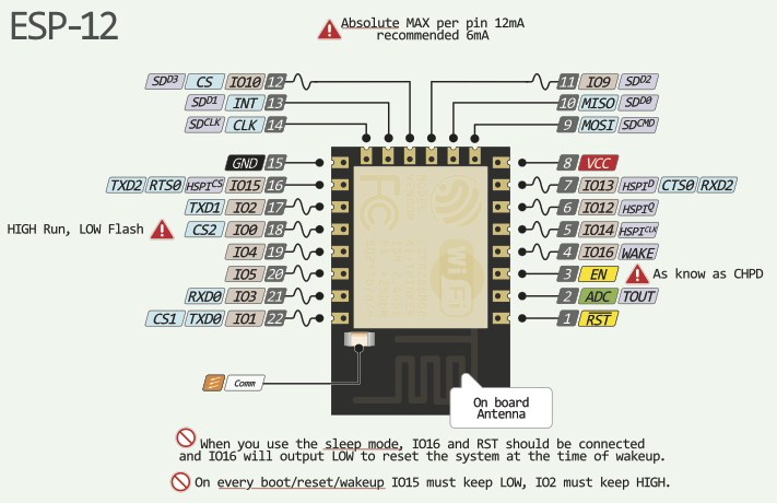
[pighixxx] started out making very pretty and functional pinout diagrams for a number of microcontrollers, and then branched out to modules and development boards like the Arduino and ESP8266. They’re great, and we’ll admit to having a printout of his SMD ATMega328 and the ESP-12 on our wall. His graphical style has been widely copied, which truly is the sincerest form of flattery.
But after pinouts, what’s next? Fully elaborated circuit diagrams, done in the same style, of course. “ABC: Basic Connections” started out life as a compendium of frequently used sub-circuits in Arduino projects. But you can take “Arduino” with a grain of salt — these are all useful for generic microcontroller-based projects. So whether you want to drive a 12 V solenoid from a low-voltage microcontroller, drive many LEDs with shift registers, or decode a rotary encoder, there is a circuit snippet here for you. Continue reading “First Look At ABC: Basic Connections”→
This is the continuation of a series of posts where I create a schematic and PCB in various EDA tools. Already, we’ve looked at Eagle CAD, KiCad, and took a walk down memory lane with one of the first PCB design tools for the IBM PC with Protel Autotrax. One of the more controversial of these tutorials was my post on Fritzing. Fritzing is a terrible tool that you should not use, but before I get to that, I need to back up and explain what this series of posts is all about.
The introduction to this series of posts laid it out pretty bare. For each post in this series, I will take a reference schematic for a small, USB-enabled ATtiny85 development board. I recreate the schematic, recreate the board, and build a new symbol and footprint in each piece of software. That last part — making a new symbol and footprint — is a point of contention for Fritzing users. You cannot create a completely new part in Fritzing. That’s a quote straight from the devs. For a PCB design tool, it’s a baffling decision, and I don’t know if I can call Fritzing a PCB design tool now.
 [Allan] starts with a basic breadboard design, draws a schematic, prototypes the circuit, then designs the PCB and orders it online, followed by assembly and testing. [Allan] had previously taught himself to use