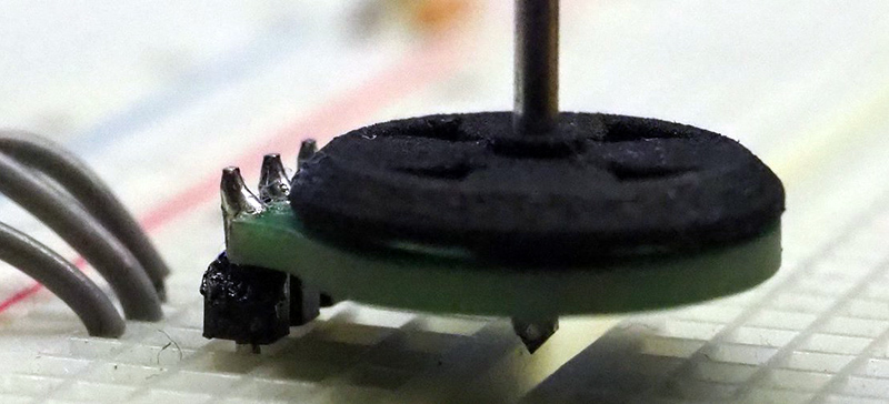
There’s something to be said about the falling costs of printed circuit boards over the last decade. It’s opened up the world of PCB art, yes, but it’s also allowed for some experimentation with laying down fine copper wires inside a laminate of fiberglass and epoxy. We can design our own capacitive touch sensors. If you’re really clever, you can put coils inside four-layer PCBs. If you’re exceptionally clever, you can add a few magnets and build a brushless motor out of a PCB.
We first saw [Carl]’s PCB motor at the beginning of the year, but since then we’ve started the Hackaday Prize, [Carl] entered this project in the Prize, and this project already made it to the final round. It’s really that awesome. Since the last update, [Carl] has been working on improving the efficiency and cost of this tiny PCB motor. Part of this comes from new magnets. Instead of a quartet of round magnets, [Carl] found some magnets that divide the rotor into four equal pieces. This gives the rotor a more uniform magnetic field across its entire area, and hopefully more power.
The first version of this 3D printed PCB motor used press-fit bushings and a metallic shaft. While this worked, an extra piece of metal will just drive up the cost of the completed motor. [Carl] has redesigned the shaft of the rotor to get rid of the metallic axle and replace it with a cleverly designed, 3D printed axle. That’s some very nice 3D printing going on here, and something that will make this motor very, very cheap.
Right now, [Carl] has a motor that can be made at any board house that can do four-layer PCBs, and he’s got a rotor that can be easily made with injection molding. The next step is closed-loop control of this motor. This is a challenge because the back-EMF generated by four layers of windings is a little weak. This could also be accomplished with a hall sensor, but for now, [Carl] has a working PCB motor. There’s really only one thing to do now — get the power output up so we can have real quadcopter badges without mucking around with tiny brushed motors.
[Carl] has put up a few videos describing how his PCB motor works; you can check those out below.


Let’s not forget https://hackaday.io/project/85502-pcb-stepper-motor
Those look like your standard hard drive magnets. Thats awesome you can find them anywhere.
Background music should be just that, in the background. Not louder than the actual points and discussion at hand. I keep seeing this more and more, how do content creators not realize we can’t hear them easily over the noise?
Honest question if it has something to do with “you spoke the words yourself, so you hear what you meant clearly, come time for post-editing, any significant background noise/music is easy for the producer to mentally filter out. But for the audience taking the information in fresh, it really does distract.
+1
What’s the use case for these?
little blower on the PCB, throw air around the components, so you have a blower just the same hight as a TO-263..
Or a micro quad-copter.. or get it fast enough to get a POV going…
Perhaps add motor controller to same pcb? Would really make compact solution!!
I saw something somewhere (Hackaday or YouTube) where you can easily make an encoder out of a brushless motor so, maybe that would be another application for this?
coils in PCBs have many extended uses beyond motors. I can’t wait to see instrument pickups made out of PCBs! or linear actuators! Cheap metal detectors!
YAY!