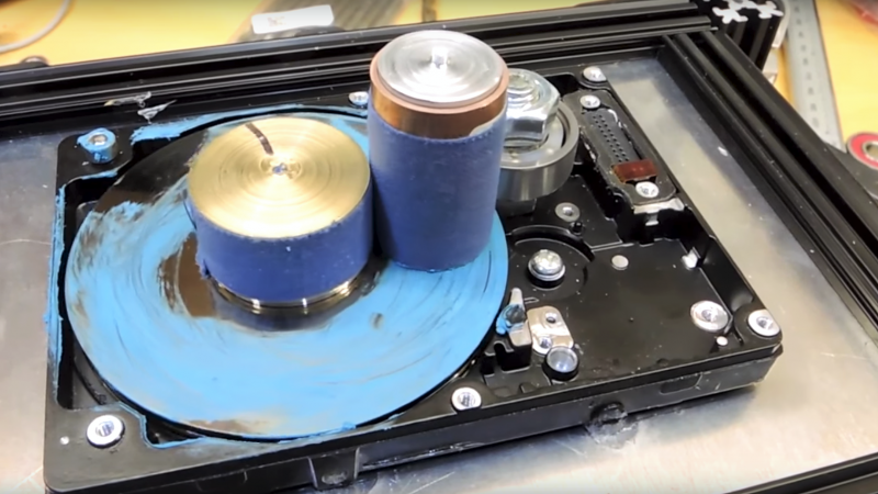
It seemed like a good idea to build a semiconductor lapping machine from an old hard drive. But there’s just something a little off about [electronupdate]’s build, and we think the Hackaday community might be able to pitch in to help.
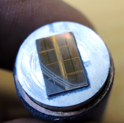 For those not into the anatomy and physiology of semiconductors, getting a look at the inside of the chip can reveal valuable information needed to reverse engineer a device, or it can just scratch the itch of curiosity. Lapping (the gentle grinding away of material) is one way to see the layers that make up the silicon die that lies beneath the epoxy. Hard drives designed to spin at 7200 rpm or more hardly seem a suitable spinning surface for a gentle lapping, but [electronupdate] just wanted the platter for its ultra-smooth, ultra-flat surface.
He removed the heads and replaced the original motor with a gear motor and controller to spin the platter at less than 5 rpm. A small holder for the decapped die was fashioned, and pinched between the platter hub and an idler. It gently rotates the die against the abrasive-covered platter as it slowly revolves. But the die wasn’t abrading evenly. He tried a number of different fixtures for the die, but never got to the degree of precision needed to see through the die layer by layer. We wonder if the weight of the die fixture is deflecting the platter a bit?
Failure is a great way to learn, if you can actually figure out where you went wrong. We look to the Hackaday community for some insight. Check out the video below and sound off in the comments if you’ve got any ideas.
We’ve seen a fair number of [electronupdate]’s teardowns before, like his look inside an SMT inductor, and of course [Ken Shirriff] has done a lot of work under the hood of ICs over the years. It’s fascinating stuff, and we hope he gets the kinks worked out and reveals what lies beneath.


I used to do de-processing at Intel to verify schematics.
There’s a special trick to mounting ICs and particular (simple) mechanical device to mount the chip.
You should mount dice with this if no already: https://www.google.com/search?q=crystal%20low%20melt%20mounting
You should be using a known planar surface along with the crystal bond to make sure the dice surface and crystal bond are level
You should be using a tripod polisher similar to this: https://www.laddresearch.com/general-laboratory-supplies/tripod-polisher-for-tem-and-sem-accessories
Additionally, have multiple sizes of lapping and various hardness abrasives on hand: https://www.google.com/search?q=10%20micron%20lapping%20abrasive
And the wheel should be covered with this: https://www.google.com/search?q=10%20micron%20lapping%20abrasive
You may or may not be doing all these things but I didn’t have to time to deep dive to see how you guys work.
If you’d like to know more please contact me directly by email.
There’s a couple of techniques that I can share that should help eliminate the destruction of the corners of the parts.
You should write an article about IC deprocessing ;) I’m planning to delayer some PCBs, and would like to learn how you manage to limit corner over-abrasion.
Just as @acabx has requested, please create a tutorial for this. I have been down this path myself but had to abandon it multiple times due to the low yield.
What about, in essence, flipping things upside down? Go for a belt drive setup with the platter free rotating on a rod allowing for uninhibited vertical movement.
The edges wear out faster because the sample rotates and the grinding speed around the perimeter is greater.
The abrasive paste pools around the edges, tilting the sample gently.
http://www.huanair.com/UpLoad/201609/2016090753629729.jpg
Notice in a commercial machine, the samples aren’t simply rotated, they’re brought in and out through the grinding disc.
On the commercial machines the samples are placed in holes in a ‘sample holder disc’ located right above the abrasive. The sample holder disc is moving the samples around while the abrasive disc is also rotating. The sample holder disc has to be relatively close (in height) to the abrasive disc to minimise tilting of the samples. To see some videos, search ‘tegrapol’ on youtube.
In the experimental setup, the problem might be slight tilting of the sample because of the design of fixing and rotating system.
This is the right answer. I lapped hydraulic port plates for years, optically flat. We used multiple rotating rings to move the point of contact. He may also have too much weight, leading to heat generation and deformation of the center of the die, the edges would stay cooler than the center leading to uneven contact.
” I lapped hydraulic port plates for years, optically flat.”
Whoa! Slow down Coach! You’re going to fast for me!
Hydraulic port plates?
Well, you don’t want your spurving bearings to delaminate, do you?
Here’s a thought, probably a wrong one.
The surface of the hard drive disk is smooth so the oil based lapping compound will have a tendency to bead on the surface. Then as the puck moves on the surface the rotation and surface tension of the lapping compound will keep most of the abrasive away from the center of the puck.
Suggestions:
1)Lower the surface tension of the lapping compound
2)Abraid the surface of the hard disk platter to prevent the meniscus from forming
Commercial wheels have a compliant compressed foam disc that ‘suspends’ the particles so they all ‘grind’ with even pressure.
Edge speed higher than center speed is a good first thing to consider, but also consider that the bearings in a hard drive are not designed to bear a lopsided load (especially one that’s always trying to twist the axis of rotation to one side) and those bearings are also designed for a light load at high speed and so may count on fluid dynamic facors inside the bearing coupled with gyoscopic stability from the platters themselves to have the stability.
I bet you’d have better luck with a trailer spindle and hub with its beefy conical rolller bearings and tapered spindle. None of that solves the surface speed proportional to radius issue though, but the further out from the center you go the smaller the proportional difference is between a pair of points a millimeter apart though.
Long ago and far away I spent way way too much time lapping mineral sections as a geology undergrad. We were working to get them seriously flat. Like optically flat. Everything was lapped by hand in a figure 8 pattern to avoid the working one edge more than another problem that you see here. The problem is that it sometimes still ended up thinner at the edges than the centre. The only thing that fixed that was more time and practice.
Ah, the joys of (free) student labor.
Try a rotating fixture. The platter spins and the fixture rotates.
You could also use a photoresist and acid to abraise a pattern (like gravurie) on the platter, and suspend the fixture just above the platter such that the lapping compound abraises the chip but it is not under a weighted pressure with the platter.
I’d have thought a belt grinder type setup would work better for something like this? At least it wouldn’t have the off angle grinding issue.
A belt grinder is way too aggressive for the small amount of material to be removed here. It would be no where near flat enough either. Lapping is the equivalent of using like 1000+ grit sandpaper and your part takes the shape of what ever your lapping it on. So the surface has to be perfectly flat For something to maintain its flatness it has to be very stiff and properly supported so gravity has minimum effect on its flatness.
Often a piece of granite is used as a flat reference in the shop. A table sized piece might be 12″ thick to give it enough stiffness. Airy or Bessel points are used to support it so that the effects of gravity are minimized.
I’m no expert on this stuff but have been enjoying learning a bit about it from Tom Lipton (oxtoolco) on youtube.
I’ve only done for machines tool finishes, and that is really polishing, and metallurgy lab micro-analysis to verify crystal/amorphous structure and characteristics where that wasn’t even as detailed as is being performed with the semiconductor devices. Interesting learning experience. Would be interesting if there was a cool laser ablation technique that would be faster, though I’m sure the surface wouldn’t be as uniform most likely.
A classmate/gf in university got a patent on the process for using laser ablation to clean/level silicon wafers prior to lithography. She is now a very wealthy woman.
There’s several factors that will introduce errors. The drive force to the sample holder introduces an off-axis force, misalignment of the guide-bearing can introduce off-axis force, flex of the HDD platter, inadequate bearing of the platter (it’s not designed for much axial load). Put it all together and this concept just won’t work. Nice idea though
He could eliminate the flex of the single platter by removing the platters and the spacer rings and then restacking them so there are no spaces between the platters.
I’m not sure that works. The discs can still slide over one another easily so increase of stiffness won’t be great. Nor will it address the possibility of play in the bearing under load at low rpm.
Dear moderator:: I’m so sorry I clicked “report” by accident when I meant to click “reply”. And apologies to chagrinnish too,
low rpm … hum … use bushing instead bearing
That only slightly helps one of the issues. Probably the least important one at that
Get good at figure-eight hand-lapping. I see no reason for the platters to stay flat
I don’t think this is issue yet but the assumption that any hdd platter is flat at the micron level might be faulty. There’s really no need for them to be. His surface plate might not be flat enough either, for this work you need AA grades. The other errors seem more likely for now but it could be an issue later.
Lots of reasons for them to be that flat. The flatter they are the closer the heads can get to the real surface and the more data you can squish in.
But this is just not a good design, platters are flimsy. Used lapping machines are not that hard to find.
The surface finish may be good, but the overall shape of the platter need not be flat. It can taper towards the edges to shave off some of that inertial load, for example.
HDD R/W heads are operating in ground effect / thin film hydrodynamic mode. That only requires 0.0004″ , micron resolution is 0.00004″ so there’s an order of magnitude difference in the flatness required.
All of you, stop fixating on platter flexing, when his axis of rotation is constrained by flexible cloth (that blue bands) and it can wobble by 0.5mm… THAT looks like the biggest source of unevennes.
I am refreshed to see so many helpful comments and suggestions!
The method shown uses the surface being ground away as its own reference, which is basically the same problem as balancing an inverted pendulum.
You can only assume the surface exposed after one revolution’s worth of grinding is parallel to the original surface if you also assume material is removed uniformly across the whole surface. Any deviation from perfectly uniform removal gives you a new surface that isn’t parallel to the original one, and that becomes your reference for the next rotation.
Techniques like figure-8 grinding and rotation of the blank relative to the grinding surface try to keep the amount of material removal uniform, but it’s still a balancing act.
The alternative is to constrain the surface being ground so it can’t rotate. Then the rate of material removal will be inversely proportional to the distance between the surface to be ground and the grinding surface, and areas that grind away faster will basically shut themselves off until the other parts catch up.
For short-throw applications, it’s easiest to build a parallel-motion system from flexures: make two L-shaped pieces of sheet metal and mount three equal-length posts between them at the ends and the corner of the L. You’ll end up with two parallelograms that share a common edge and have an angle between them.
If you lock the two free ends in place, only the post at the corner can move, and it can only move in a way that keeps it parallel to the fixed posts. For small displacements it will behave very much like a frictionless linear bearing.
You don’t even have to be careful about making the corner post perpendicular to the grinding surface. Set the chip on the grinding surface so its original face provides a reference plane, use glue to fill the space between the top of the chip and the bottom of the post, and you’re good. The parallel motion of the post constrains the surface to be ground so it can only move parallel to its original position.
Assuming you’re very patient couldn’t you just live with it.
Grind a bit take a photo… Grind a bit more… Take another photo etc.
Then selectively stitch photos together to get layers. The stitching could be automated, the grinding and then photographing might be a pain though.
A bit late, but still want to add my own 2ct.
Getting to sub um flatness is no small feat, but why would you want to for deconstruction?
Just lap of an (average) sub layer thickness and take lot of intermediate pictures.
Then later you can reconstruct the individual layers from multiple pictures.