
When you first learn about digital logic, it probably seems like it is easy. You learn about AND and OR gates and figure that’s not very hard. However, going from a few basic gates to something like a CPU or another complex system is a whole different story. It is like going from “Hello World!” to writing an operating system. There’s a lot to understand before you can make that leap. In this set of articles, I want to talk about a way to organize more complex FPGA designs like CPUs using a technique called pipelining.
These days a complex digital logic system is likely to be on an FPGA. And part of the reason we can get fooled into thinking digital is simple is because of the modern FPGA tools. They hide a lot of complexity from you, which is great until they can’t do what you want and then you are stuck. A good example of that is where you are trying to hit a certain clock frequency. If you aren’t careful, you’ll get a complaint from the tool that you can’t meet timing constraints.
There are many possible reasons this can happen, but probably the most common is you are just trying to do too much on each clock cycle. While we tend to think of our circuits as perfect, they aren’t. The logic gates are fast — very, very fast — but they are not infinitely fast. On larger chips, even the time for a signal to get to one part of the chip to another becomes significant.
The modern tools have great models for how long everything takes worst case and helps you by figuring out cases where things won’t work reliably. Consider this circuit:
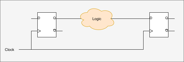
The cloud represents a bunch of combinatorial logic like AND and OR. Could even be a lookup table, it doesn’t matter. If the delay from the input of the box to the output is shorter than the clock pulse, all is well. But if the signal on the right-hand flip flop’s D input is still in transit before the clock pulses again, you’ll get bad behavior. In fact, it is a little more complicated than that. The signal actually has to beat the clock by the flip flop’s setup time and stay stable over the hold time, both things the software knows about. We’ve talked about this in depth before. But for the purposes of this article, the key idea is the transit delay of our logic “cloud” has to be shorter than the clock timing.
Let’s say you have your heart set on a 100 MHz clock but the tool tells you that you can’t get there. Your logic is too slow. What can you do? One answer is pipelining.
Logic Traffic Jams
I often think a better term for a pipeline in this context would be a bucket brigade. The idea is to do a little work each clock cycle and then hand that off to another part of the chip. You see CPUs do this all the time. For example, a typical 8-bit Microchip PIC CPU does one instruction every four clock cycles. But some PIC clones (like the old Ubicom SX) could do an instruction every clock cycle and the clock speed was generally faster.
Consider a hypothetical CPU. It executes instructions in four steps:
- Fetch instruction
- Fetch arguments
- Do operation
- Write results
I’m glossing over a few things, but that is actually pretty close to accurate for a lot of CPUs. You have two choices. You could try to do everything in one clock cycle but that would be a nightmare. Suppose you are doing step 2 and one argument is the accumulator which takes 33 picoseconds to arrive at the logic that does the operation in step 3. But the register argument takes 95 picoseconds. Then the execution logic takes some time. When do you do step 4?
The only way to handle that would be to figure out the absolute longest time it would take for the answer in step 4 to be correct and limit your clock speed to that. It isn’t going to be very fast.
A much more common approach is to do one step during one clock cycle. Then do the next step in the next clock cycle. This effectively divides the clock by four since each instruction now requires four clock cycles, instead of one.
You could set up a counter that goes from 0 to 3 so you know what part of the processing you are doing. Or, you might use a one-hot scheme where each state has its own flip flop. Then the CPU does what it has to do and only that part of the logic has to finish before the clock strikes again. Really, it is the same problem as before, except the total time in each tick is less and you have to keep your clock slower than the slowest section. In some cases, a very slow section (like step 1) might introduce wait states so that you stay in that step longer, but you don’t see that as much as you used to when memory was slower and dynamic RAM refresh cycles were longer.
This works and it is a common way to do things. Probably exactly what is happening inside a PIC. But if you think about it, if all the steps take about the same amount of logic, then 3/4 of the device is doing nothing most of the time. While step 2 occurs, all the logic for the other steps is doing basically idle.
Pipelines
That’s where pipelining comes in. Imagine if instead of a counter that activates one of the four steps we put flip flops between each step. Consider executing four instructions: A, B, C, and D. The CPU resources would look like this:

See how it is like a bucket brigade? Each section does its thing and then hands off to the next section. This lets all the sections work on something all the time.
The general idea is to break the logic into chunks that are independent. Then put flip flops on all the outputs. This lets each section generate a result on each clock cycle that the flip flop then holds for the next chunk. Presumably, the chunks are significantly faster than the overall processing. If the Step 3 logic was, say, 95% of the time delay, you wouldn’t get much help from this technique.
Exactly how you do this will depend on what you want and how you want to build your logic in each step. Next time I’ll show you an example where each step takes a clock cycle. However, it is possible to let the processing in the block use a higher clock frequency and then use a slower clock enable signal for the pipeline. In that case, the output of one step can only change when clock enable is asserted.
All that assumes that each stage needs the same amount of time, too. In some cases, you’ll add “do nothing” stages to the pipeline to handle the case where a step requires more than one clock cycle. The no operation stages go before the slow stage, of course. Another alternative is to place a FIFO buffer between stages, which is often available as a ready-made block in your design environment.
You can also design each stage so it signals when it has valid data for the next stage. In a complex case, you can even have the stages handshake like a serial port. Step 2 could signal step 1 it is ready for more data and step 1 can signal when that data is valid. This can also combine with FIFO buffers if you want to make your pipeline super complex.
There are probably many more approaches you could devise, but the principles are the same. The issue with buffering and handshaking is that it further drives the logic complexity up which hurts speed and eats up FPGA resources. You have to balance the cost of the additional complexity against the benefits.
No Free Lunch
Going back to the simple pipeline, now we get one instruction per clock cycle and the processing chunks are smaller, so we can easily have a faster clock. This might seem like getting something for nothing — well, for very little, anyway — but it isn’t. If you are observant, you’ll notice that while we get one instruction per clock, there is also a big latency from the start of execution until the time that instruction A completes. Of course, since the clock is faster, that latency is really about the same as the unpipelined clock speed.
There are some other issues. Obviously, you add complexity. For a CPU, there are other concerns known as hazards. A complete discussion of hazards would have to start with some CPU design basics so that’s beyond the scope of this article, but consider this: If step 2 of instruction B has to read something that was written by instruction A, how would that work? Instruction A hasn’t made it to step 4 yet. In some cases, the solution is to stall the pipeline. In others, there is a way to steal the result from the pipeline early.
 Another complexity you are probably aware of is filling the pipeline. In all modern processors, there is a penalty for making a conditional branch. You want to do, for example, a jump on zero instruction. But after you fetch it, where do you fetch the next instruction? If you grab the next instruction, there is some chance the jump will occur and that instruction won’t execute. If you grab the one that the jump references, you’ll still be wrong some of the time. Different designers do different things. Some try to predict the branch. Others just pick a strategy (usually get the next instruction) and stick to it. Skip instructions are often provided because the CPU can invalidate one instruction instead of the entire pipeline (unless the skipped instruction is a jump, of course).
You also have to make sure when you jump that any instruction that was in the middle of the pipeline at the time of the jump is not just discarded but also had no effect on the machine’s state before you dumped it. In CPU design lingo, the instruction doesn’t commit until you are sure it really executed.
I’ve used a lot of CPU examples because they are common. But these issues are true even if you are doing something that isn’t a traditional CPU. You have to make sure the pipeline is filled with the right instructions and that data is available when you need it.
Next Stop: Working Example
All this is great in theory, but how about a practical example? I’m going to use Verilog which has great features for modeling delays in circuits. Next time, I’ll explain how that works and show you an actual example of “computing” a value inside an FPGA and using pipelining to make it faster. You can play with the example using any Verilog simulator of your choice, but I’m going to use EDAPlayground. It is great for running little tests or demonstrations and gives you a wide range of tools right in your browser.
By the way, a good example of a non-pipelined CPU is Blue, which I’ve talked about before. The clock generator uses a one-hot scheme to produce 8 clock enables that govern what part of the instruction execution is underway. The chip does one part of the execution per clock, so the clock speed is essentially 1/8 of the clock input frequency.
See you next time!


The Intel Prescott P4 had 31 pipeline stages. They were able to bump the clock speed which was good for marketing but not much else.
Didn’t the old PIC16c84 work like this?
pipelining is like trying to optimize a java program. Even the most 100% optimized java program will run as fast as frozen molasses. Either double the bus width, or add more dedicated hardware.If you need to pipeline, you need to calculate the latency penalty. Cycles count.
In many cases throughput is important but you really don’t care about latency. Pipelining is an important technique to meet timing or improve throughput.
Pipelining or in its simplest form, buffering is required for IP reuse. One can not design and maintain syntheziable IP blocks without this. If fpga logic is pain to design, the asynchronous desing is nightmare. I would like to see one trying to verify timing constraints with fully asynchronous 3 rd. party IP blocks …
Meh… Did this already ten years ago :-)!
LOL what? I did this eleven years ago.
??? Pipelining has been around for a long time. Longer than a decade. What are you trying to tell us?
⟶[Buffer]⟶[Stage 1]⟶[Buffer]⟶[Stage 2]⟶[Buffer]⟶[Stage 3]⟶[Buffer]⟶[Stage 4]⟶
I thought you grabbed the jump AND non-jump destination code, then dumped whichever path became invalid.
There are many strategies. Depends on the CPU. Some look at if the jump was taken historically, for example. Some do get both, but unless your memory system is supercomputer grade or the paths are close together (within a cache line) you aren’t going to be able to do this effectively because you’ll stall on the second memory access.