Somehow, walking robots at our level never really seem to deliver on the promise that should be delivered by all those legs. Articulation using hobby servos is simple enough to achieve, but cumbersome, slow, and not very powerful. [Paul Gould] has a plan to make a better, 3D-printed articulated robot actuator.
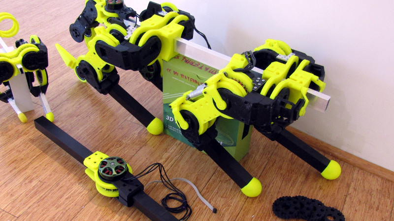
His solution is both novel and elegant, a fairly conventional arm geometry that has at its joints a set of brushless motors similar to but a little larger than the kind you might be more familiar with on multirotors, paired with 3D-printed cycloidal gearboxes. Magnetic encoders provide the necessary positional feedback, and the result is a unit that is both compact and powerful.
With such a range of small brushless motor controllers on the market, it’s at first sight unexpected that he’s designed his own controller board. But this gives him complete control over his software, plus the CAN bus that ties everything together. He’s given us a video which we’ve placed below the break, showing the build process, the impressive capabilities of his system, and a selection of builds including a robot dog complete with tail. This is definitely a project to watch.


Now that’s how you do it, not with ball screws like last one.Great design!
Ballscrews are much better because they have pretty much zero backlash – you can position your robot very exactly.
I think the problem is that exact positioning isn’t the goal – it’s having a dynamically adaptive walking cycle like living creatures.
Ballscrews are excellent for positioning but perhaps not for robotic limbs.
What a nifty and compact gearbox. Really nice work! any plans to mill the gears out of metal in future iterations?
I’m in two minds about this. I want everyone to be about to make the actuator easily, no special tools/parts required. The ABS printed gears have handled 10Nm of torque so far.The forces are spread over a large number of teeth. I will try Nylon filament next. Separate to this, I was thinking of getting a quote to make 50 or 100 Aluminium gears in Taiwan/China.
I wonder if your local makerspace might have milling capabilities… ;)
When I see people’s robot projects I often think, you’re never going to get it to walk fluidly let alone run without the mechanics being able to actuate quickly, precisely and with power. This project nails it! Its got speed and torque! You can measure position accurately so with the control system you can get accurate positioning. Brilliant! I love this design. I look forward to seeing it in action.
Also a design win is that 3D prints are used where needed and not where other parts are superior. Far to often we see 100% 3D printed robots for convinence even if its more cost efficient and better material properties to use other readily available parts/materials for large sections of the system.
3d printing is for mechanics what FPGA is for electronics. Sure you can use it for the entire system, but its often better to use readily available parts and use the 3d print or FPGA to connect the parts.
That’s one very nice design, seems to work pretty well.
I visited the youtube page and noticed another very interesting video regarding a robot hand.
https://www.youtube.com/watch?v=_P160S7XQl8
Very, very cool stuff!
I got to the point where I added a 2-DOF shoulder and got it throwing a little ball about 1 metre. I have put the hand on hold while I make other robots.
Awesome stuff. Thanks for posting. I’m just starting to get into this space and trying to wrap my head around everything. Seeing projects like this really help!
I know cycloidal gearboxes aren’t commonly very backdriveable . How backdriveable are yours? If they aren’t very backdriveable how do you plan (if at all) on adding compliance to your joints?
It is easily backdriveable because of the relatively low ratio reduction (only 26:1) and everything has a bearing or bushing. The large quad has a parallel linkage series elastic actuator for each hip/knee joint. So I am hoping that I can get mechanical energy storage as well as electrical storage with hybrid supercaps.
Great actuator , if you can incorporate a rotary optical encoder , that could possibly add to the precision of the movment and would be a great feedback loop for the motion
I don’t see the need for an optical encoder. There are two absolute magnetic encoders in this actuator. One for the motor position, so it can do Field Oriented Control and one for the final joint position. It runs a fuzzy/PID loop on final position.
Also how small can you make this type of actuator ? The size of a knuckle? Thinking how this could affect Open source prosthetics if you can get it down small enough
I’ve made one about 44mm in diameter using 6804 bearings with a 17:1 ratio. I am sure that you can go smaller but you will have to swap bearings for bushings.
search alibaba/aliexpress for planetary gearbox. small, robust ones made for stepper motors are $30-50
Or $18 cordless drills from wal mart and pull the 2 stage planetary gearbox and either adapt to your dc motors or just use the motors that are already attached. I’m on iteration #3 of a project like this only using 20kg rated hobby servos but if this build doesn’t pan out, I will bust open the drills I bought for this purpose. I will likely be using only one stage per motor though, as these are a lot more reduction than I need for my dog robots size unless I want to power it with a ton of batteries but we will see.