A 3D Printed Cycloidal Gearbox

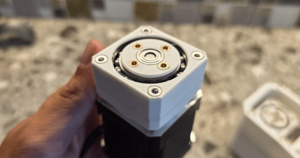
Stepper motors are undeniably useful, but sometimes they need a bit of gearing to help perform their task. [Gjhudson2008] has a compact gearbox for NEMA 17 or 23 steppers that is mostly 3D printed. How compact? The gearbox, named VANTIX, is exactly the height of a standard NEMA 17 axle.

However, for it to be that thin, your stepper has to have the D-bore on the shaft go all the way down. Some steppers leave a shank uncut at the base, and that won’t work for VANTIX.

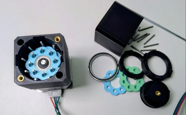
The recommendation is to print in ABS with a 0.2 mm nozzle for certain parts to help improve tolerance. Most of the assembly is either press fit or installed during the printing process. Some parts of the gearbox are better to print with a larger nozzle, too.

There are some heat-set inserts and, of course, you’ll need lube to keep everything moving smoothly. There are a few top plates you can print to fit various mounting scenarios.

We have seen a number of similar designs. We’ve also looked at some e-bike-inspired drives.

Testing A 3D Printed Cycloidal Gearbox Design

Cycloidal gearboxes are a recurring theme in the hobbyist space due to the performance they promise in a compact package. They are capable of taking in a high-speed input and reducing it down to a set ratio with very low backlash, which theoretically makes them perfect for a wide range of projects where size and weight matter. Correspondingly, [Advanced Hobby Lab] has been tinkering with a 3D printed design to fit on NEMA 17 stepper motors.

For [Advanced Hobby Lab] the primary goal was to check that his cycloidal gearbox design was a real improvement over the planetary gearbox alternative. Although the 3D printed cycloidal drive worked well enough, some testing put real numbers to it, including a 92% efficiency. The gearbox also adds some noise over the stepper motor, but less so than the 3D printed planetary gearbox.

Of course, all of this is within the limits of FDM 3D printing and with a few metal parts, so there’s always room for improvement, but in the world of hobbyist 3D printed gearboxes it’s not a bad showing. The print and project files are available for anyone who is also feeling the itch. Of course, you can also opt for the dual-nested cycloidal design that we recently featured, as it promises to be even more compact, have even fewer parts and smoother action.

Continue reading “Testing A 3D Printed Cycloidal Gearbox Design”

An Elbow Joint That Can

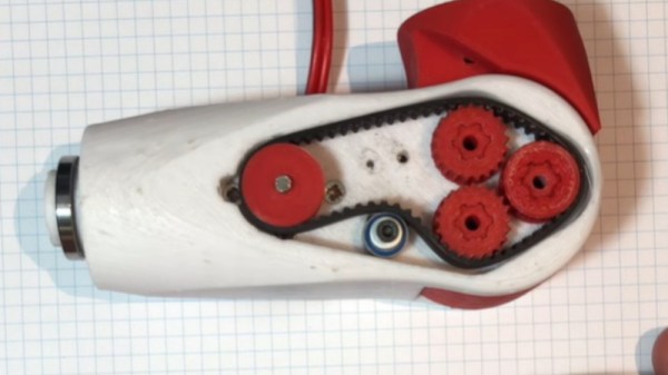
We’re not certain whether [Paul Gould]’s kid’s prosthetic elbow joint is intended for use by a real kid or is part of a robotics project — but it caught our eye for the way it packs the guts of a beefy-looking motorized joint into such a small space.

At its heart is a cycloidal gearbox, in which the three small shafts which drive the center gear are driven by a toothed belt. The motive power comes from a brushless motor, which is what gives the build that impressive small size. He’s posted a YouTube short showing its internals and it doing a small amount of weight lifting, so it evidently has some pulling power.

If you’re interested in working with this design, it can be downloaded for 3D printing from Thingiverse. We think it could find an application in plenty of other projects, and we’d be interested to see what people do with it. There’s certainly a comparison to be maid over robotic joints which use wires for actuation.

Continue reading “An Elbow Joint That Can”

Radial Vector Reducer Rotates At Really Relaxed Velocity

When [Michael Rechtin] learned about Radial Vector Reducers, the underlying research math made his head spin, albeit very slowly. Realizing that it’s essentially a cycloidal drive meshed with a planetary gear set, he got to work in CAD and, in seemingly no time, had a design to test. You can see the full results of his experiment in the video below the break. Or head on out to Thingiverse to download the model directly.

[Michael] explains that while there are elements of a cycloidal drive, itself a wonderfully clever gear reduction mechanism, the radial vector reducer actually has more bearing surfaces, and should be more durable as a result. Two cycloidal disks are driven by a planetary gear reduction for an even greater reduction, but they don’t even spin, they just cycle in a way that drives the outer shell, setting them further apart from standard cycloidal drives.

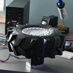
How would this 3D printed contraption hold up? To test this, [Michael] built a test jig with a NEMA 23 stepper providing the torque, and an absurd monster truck/front loader wheel — also printed — to provide traction in the grass and leaves of his back yard. He let it drive around its tether for nearly two weeks before disassembling it to check for wear. How’d it look? You’ll have to check the video to find out.

If you aren’t familiar with cycloidal drives, check out this fantastic explanation we featured. As for planetary drives, what better way to demonstrate it than by an ornamental planetary gear clock!

Continue reading “Radial Vector Reducer Rotates At Really Relaxed Velocity”

Do You Need A Cycloidal Drive?

A cycloidal gear drive is one of the most mesmerizing reduction gears to watch when it is running, but it’s not all just eye-candy. Cycloidals give decent gearing, are relatively compact and back-drivable, and have low backlash and high efficiency. You probably want one in the shoulder of your robot arm, for instance.

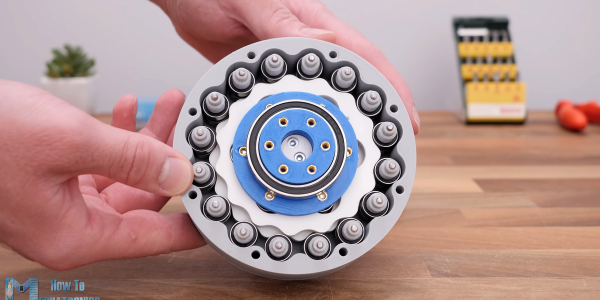
But designing and building one isn’t exactly straightforward. Thanks, then, to [How To Mechatronics] for the lovely explanation of how it works in detail, and a nice walkthrough of designing and building a cycloidal gear reducer out of 3D printed parts and a ton of bearings. If you just want to watch it go, check out the video embedded below.

The video is partly an ad for SolidWorks, and spends a lot of time on the mechanics of designing the parts for 3D printing using that software. Still, if you’re using any other graphical CAD tool, you should be able to translate what you learned.

It’s amazing that 3D printing has made sophisticated gearbox designs like this possible to fabricate at home. This stuff used to be confined to the high-end machine shops of fancy robotics firms, and now you can make one yourself this weekend. Not exotic or unreliable enough for you? Well, then, buy yourself some flexible filament and step on up to the strain wave, aka “harmonic drive”, gearbox.

Thanks to serial tipster [Keith] for the tip!

Continue reading “Do You Need A Cycloidal Drive?”

OpenDog Version 3 Is Ready To Go Walkies

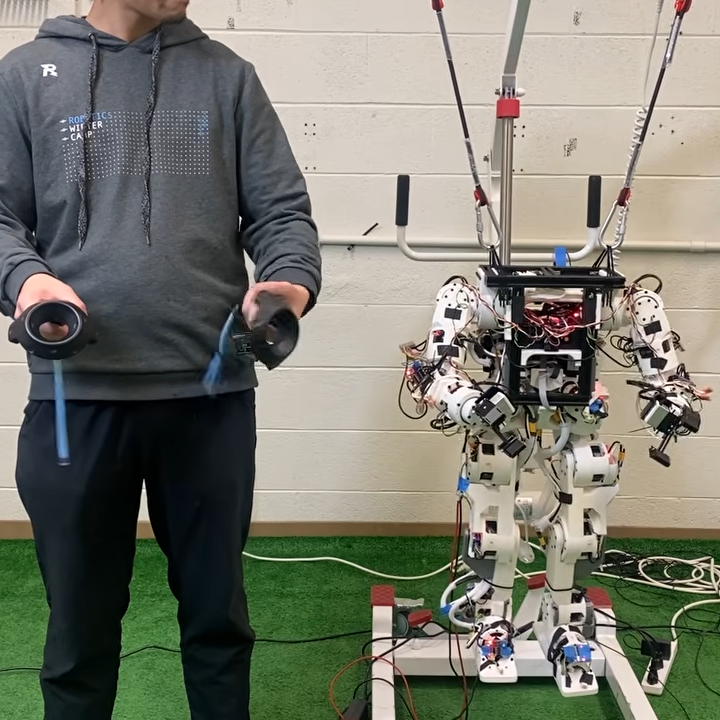
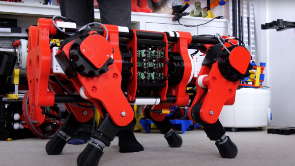
We’ve been following [James Bruton]’s open dog project for a little while now, and with his considerable pace of work – pandemic or no pandemic – development has been incredibly rapid. The latest milestone is the public release of version 3 (Video, embedded below.) This upgrade to the system adds 3D printed cycloidal gearboxes, removing the previous belt drives. [James] had immense fun tuning the motor controller parameters for these and admits they’re not completely dialed in yet. He notes that the wider gearbox body means that the robots geometry needed to change a little, and the previous belt-drive version may have a bit of an edge, but he’s confident he can make it work (and given his incredible previous robotics builds, we totally believe he’ll nail it!)

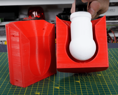
Silicone overmolding around a 3D printed former, using a 3D printed mould

Older versions struggled with slippery plastic feet; the advantage of a predictably smooth contact shape of a rounded foot is somewhat offset by the limited contact patch size, and that means not so much grip on some surfaces. [James] solution was obvious enough – just learn how to make 3D printed silicone moulds and cast a nice rubber foot around a plastic former, and problem solved! Unfortunately he neglected to add some recesses for a lever to get in between the mould halves, so it was a bit of a struggle to separate after curing. A beginner’s mistake that won’t be repeated, we’re sure.

Full source for openDogV3 is now available on the GitHub page. Here’s the playlist for the whole project, as well as direct links for the cycloidal drive development (part1, part2, part3.) But before you all go diving in to start 3D printing your own pooch, [James] tells us that the total cost would be around $2000 all in, with the bulk of that being the motors and ODrive units, so this one for the serious builder only!

We’ve covered robot dogs a fair bit, a particularly nice example is The Dizzy Wolf, and if you’re wondering just why on earth you’d want a robot dog, then Ask Hackaday has you covered as well.

Continue reading “OpenDog Version 3 Is Ready To Go Walkies”

Sixi 2, An Open Source 3D Printable 6 Axis Robot Arm

[Dan Royer] is taking some inspiration from Prusa’s business and is trying to build the same sort of enterprise around open source 3D printable robot arms. His 6 axis robot arm is certainly a strong first step on that road. 

As many people have learned, DIY robot arms are pretty difficult.  [Dan]’s arm has the additional complexity of being 3D printable with the ambitious goal of managing a 2kg payload at 840mm of reach. He’s already made significant progress. There’s a firmware, set of custom electronics, and a Fusion 360 project anyone can download and checkout. You can even control it with an Xbox controller.

The main board is an Arduino shield which outputs step and direction signals to stepper drivers. The gears are cycloidal and it appears there’s even some custom machining going on. When the parts are all laid out it becomes clear just how much effort has been put into this design.

It should be a pretty nice robot and might finally spur some of us to build the Iron Man style robot assistants we’ve always wanted. You can see the robot in action after the break.

Continue reading “Sixi 2, An Open Source 3D Printable 6 Axis Robot Arm”