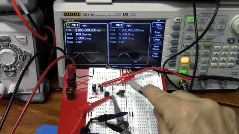
The phase locked loop, or PLL, is a real workhorse of circuit design. It is a classic feedback loop where the phase of an oscillator is locked to the phase of a reference signal using an error signal in the same basic way that perhaps a controller would hold a temperature or flow rate in a physical system. That is, a big error will induce a big change and little errors induce little changes until the output is just right. [The Offset Volt] has a few videos on PLLs that will help you understand their basic operation, how they can multiply frequencies (paradoxically, by dividing), and even demodulate FM radio signals. You can see the videos below.
The clever part of a PLL can be found in how it looks at the phase of two signals. For signals to be totally in phase, they must be at the same frequency and also must ebb and peak at the same point. It should be clear that if the frequency isn’t the same the ebbs and peaks can’t line up for any length of time. By detecting how much the signals don’t line up, an error voltage can be generated. That error voltage is used to adjust the output oscillator so that it matches the reference oscillator.
Of course, it wouldn’t be very interesting if the output frequency had to be the same as the reference frequency. The clever trick comes by dividing the output frequency. For example, a 100 MHz crystal oscillator is difficult to design. But taking a voltage-controlled oscillator at 100 MHz (nominal) and dividing its output by 100 will give you a signal you can lock to a 1 MHz crystal oscillator which is, of course, trivial to build.
The real detail lies in the phase comparison and the loop filtering, something that will make more sense once you have watched the videos.
Based on video views, [The Offset Volt] may be the best YouTube channel people aren’t watching much. The videos are clear an easy to understand! He’s even worked in a reference to a self-sealing stem bolt, so we can’t help but be impressed with that.
Our resident video star [Bil Herd] did a talk on PLLs a good while back. If you’d rather read and want to see how a PLL works in software, we’ve talked about that, too.


What I learned about PLLs long ago was that loop filters are tougher than they look….
Great talk, Bil!
The internet created our bad habit of ignoring every video expressed as N×10 minutes, but this is worth every moment of watching.
Technical talk here, please define correctly: “Where N is a positive integer greater than 1”
Or in my case where N*10 is a positive integer greater than 1.
:)
Can hardly wait for the first video where N is imaginary.
:o)
That’ll be a great twist to make it real again.
There’s a whole channel of them on the alternative eyoutube server at 127.0.0.√-1
There’s an old book “design of phase locked loops with experiments”. Most of the control logic could be emulated in an FPGA – and most larger FPGAs have a PLL or two, anyway.
Maybe it’s time to re-work that book, as a series of Verilog / VHDL expreiments?
Could certainly be done, and would make a great syllabus for a hands-on final year / graduate module on PLLs. Prototyping a PLL using an FPGA used to be quite normal, but with the off-chip parasitics performance is now nowhere near what you’d get with an integrated PLL + VCO.