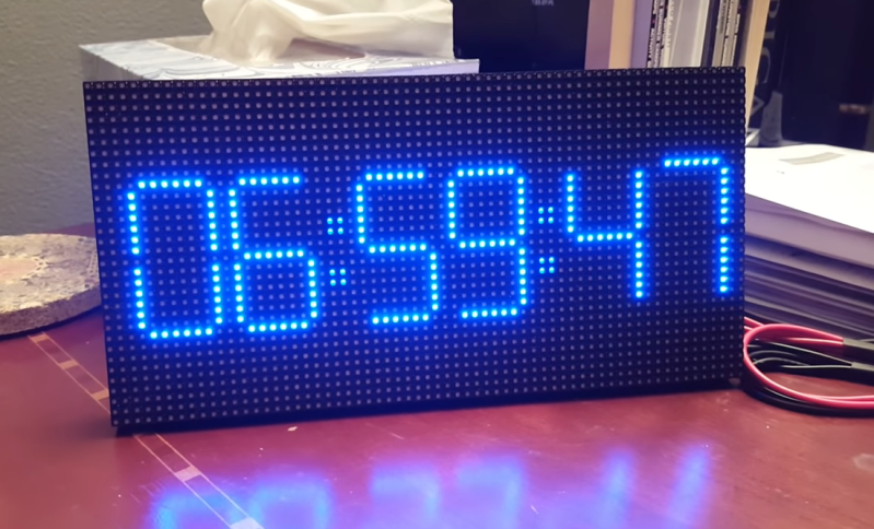
A few weeks ago, [HariFun] set out to emulate a 7-segment display with an LED matrix. Seems easy enough, right? Right. He also wanted to come up with a new way to transition between digits, which is a much harder task. But he did it, and it’s really cool. At a viewer’s suggestion, [Hari] used the transition as the basis for a mesmerizing clock that brings the smooth sweep of an analog second-hand into the digital age.
This is the coolest way to watch the time pass since the hourglass. You can almost hear the light move as one digit slides into the next. Each transition is totally unique, so depending on the digit this involves one or more vertical segments sliding from right to left, or multiple segments moving in a counter-clockwise circle.
You too can watch time glide by with little more than a 64×32 RGB LED matrix, a NodeMCU, and [Hari]’s digit transition code. It only costs about $25 to build, and you really can’t beat the quality of instruction he’s put together. Take a second or two and check it out after the break.
If you prefer OLEDs and vertical transitions, there’s a clock for that, too.


[Hari] has often mesmerizing ideas with very simple things. Typically, a Youtube channel that merits more attention. Live long and prosper, [Hari]
Very kind of you. Thank you. Live long and Make. lol
That is neat!
I’m thinking maybe using just LEDs for the 7 Segments and have them “snake” into the next number.
Oh, that’s a cool idea! Please share here if/when you do that! I’d love to see it.
Like this one I crafted?
https://www.youtube.com/watch?v=HBvKz9nJT-w
That is an excellent visualizatoin! Kudos to [Hari] for coming up with such a pleasing way to present what could have been mundane. This is what I like about our community, the little touches of craftsmanship are so pleasing.
Hi Mike!
Thanks for the comment Mike. It means a lot to me to be noticed by a celebrity. :-)
Now just think if it had been mighty morphing?
Maybe…It IS a 64×32 RGB display after all, so there’s room for explosions. But, those explosions probably would get pretty annoying after about 30 seconds. lol
You could do it once an hour or something :)
Or – even better – “celebration mode” at the end of the work day :P
https://www.youtube.com/watch?v=PxVekSvcsgQ
Hi cbm80Amiga! Thanks for sharing your version here too. Pretty amazing that you fit that code on a Nano.
I’m not cbm80Amiga.
I just recently saw this one and share this other clock concept that i also quite like.
I should have mentioned in the first place :) I find this both clocks projects fascinating.
Oops, sorry to jump into conclusion. Thx for posting anyway. The more the merrier! :-)
Looked like Morphine Digital clock will show you a good time.
Kristina, thanks for sharing my humble project on Hackaday! I was attributing the spike on my YouTube channel to Instructable, but I think true credit goes to you for pointing the large Hackaday readership to my Instructable. So, thank you!
There are already other makers who commented that they’ve purchased parts to build the clock! It’s very rewarding to inspire other makers. So, thank you again! Live long and make!
Nice one Kristina.
Ordered the rgb panel myself to do this project and I’m sure it’ll get here when money’s tight and the wife gives me hell for it
I tried generalising Hari’s 7-segment matrix display morphs to allow transitions between any arbitrary pair of digits. The extended algorithm can also handle morphs between a small set of alphabet characters that were displayable in 7-segment form.
https://youtu.be/QJZRKHw6bcg
Hi Adrian! I recognize that! Thanks for posting your version here. I hope it would inspire even more people.
Great project and instructable. I’m going to order parts and build! Now out in the open and getting even more attention, perhaps it will grow legs… what else to do with that display… there is plenty of space available for the local weather, Google Calendar, etc. This is inexpensive and really useful.
Thanks!
You’re absolutely right. It is a 64×32 canvas. Just add creativity and some code :-) Have fun!
Nice effect – but there are a couple of things I don’t understand from the instructable. You wire to R0, but the display is blue. And why are the output matrix pins looped back to the inputs? R0-R1 I could understand, but the others?
To my eye the transition time seems dependent on the amount of changes needed to be drawn (it’s observable when the whole display is redrawn when x:59:59 goes to x+1:00:00 vs last-digit-only), therefore I would personally prefer less time consuming transitions or constant-duration transitions instead of code-optimised. For example a wipe-down redrawing of the whole display.
Thanks Alphatek. I wired my matrix for all colors. The output to input is because the matrix is split into two halves, so we’re wiring the output of the first group to the input of the second group in the same matrix. Dominic Buchstaller who wrote the pxMatrix library has a detailed description of how the hardware is wired.
https://github.com/2dom/PxMatrix
Ah, right. That’s a very clever way to serialise the input stream!
Thanks so much for taking the time to code and document this awesome project. I sent the link to several coworkesr that have children, I think it’d be a great family project.
I ordered some slightly-different ESP8266s off AliExpress but there seems to be something wrong with the wifi on them… https://www.aliexpress.com/item/a/32879758161.html. Within Arduino I used the board “WeMos D1 R1” which seems to work right (it was the only one that handled the blink code properly) but when I go into config mode I never see the AP show up. Also, the wifi chip on the board seems to get VERY warm… temp of board on backside of wifi chip is about 110F while temp of board near USB port is about 90F. After getting these seemingly defective ones from AliExpress I ordered some ESP8266s off Amazon that look like the ones you had (soldered-on wifi)j.
I made a little progress and figured I’d pass it along. I Googled for ‘”HW-628″ arduino’ (HW-628 is printed on the module) which led to me to this page… http://johmon.com/blog/?p=235. This page has pictures of the HW-628 as well as screenshots of the Arduino IDE with the appropriate board chosen (“NodeMCU 1.0 (ESP-12E Module)”). It also shows them using Examples > ESP8266WebServer > HelloServer. I was able to successfully use this example as well as ESP8266WiFi > WiFiAccessPoint. So, it appears the module is function but there may be something funky with WiFiManager.