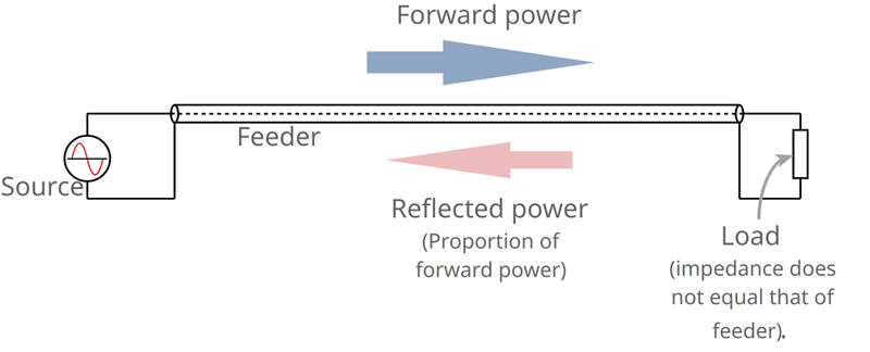
If you have ever operated any sort of transmitting equipment, you’ve probably heard about matching an antenna to the transmitter and using the right co-ax cable. Having everything match — for example, at 50 or 75 ohms — allows the most power to get to the antenna and out into the airwaves. Even for receiving this is important, but you generally don’t hear about it as much for receivers. But here’s a question: if a 100-watt transmitter feeds a mismatched antenna and only delivers 50 watts, where did the other 50 watts go? [ElectronicsNotes] has a multi-part blog entry that explains what happens on a mismatched transmission line, including an in-depth look at voltage standing wave ratio or VSWR.
We liked the very clean graphics showing how different load mismatches affect the transmission line. We also liked how he tackled return loss and reflection coefficient.
There was a time when driving a ham radio transmitter into a bad load could damage the radio. But if the radio can survive it, the effect isn’t as bad as you might think. The post points out that feedline loss is often more significant. However, the problem with modern radios is that when they detect high VSWR, they will often reduce power drastically to prevent damage. That is often the cause of poor performance more so than the actual loss of power through the VSWR mechanism. On the other hand, it is better than burning up final transistors the way older radios did.
Measuring VSWR without a transmitter is a bit trickier. A network analyzer can do it. While that used to be a pretty exotic piece of gear, it has become much more common lately.


Boy, back in my day, we had pi networks in the rigs that matched tubes to the antenna and transmission line. Funny how the concept of “tuning up” a rig is like using a rotary dial on a phone. Something a lot of today’s kids will never do.
Unless they buy a HW-101 off ebay.
That was my first rig back in 1977. I miss it sometimes. Also had an SB102 which was an underrated radio.
There are a couple of other ways to deal with reflected power in order to prevent damage that I am aware of. One way is to use a 3-port ferrite-based device called a circulator with one of the ports connected to ground and the other two connected to the transmitter PA and antenna. In this configuration it is referred to as an isolator. You can also find the same type of device in a 2 port form. This is also called an isolator.
Unrelated note: the 3 port device (circulator) can also be used for separating RX from TX paths to the antenna in applications like an RFID transceiver reading passive RFID devices where a high power TX CW signal sharing an antenna with the RX side would normally drown out the RX side that needs to detect signals many many orders of magnitude less from the reflected power of the passive RFID tags.
The second way (that I am aware of) to prevent PA damage is a balanced amplifier design via 90 degree hybrid couplers. The main advantage of this type is when you are designing an amplification chain that needs to be linear for higher order modulation schemes like OFDM/QAMxx. The other advantages are that you don’t need to worry to much about characteristic impedance matching of the amplifiers themselves as long as they are matched. The isolated port can be connected to a resistor with a value of the characteristic impedance. Lets say that the isolated port resistor is 50 ohms. In this case, the input will look like 50 ohms to the stage before the input hybrid coupler and any reflected power coming back toward the output side of the hybrid coupler will be absorbed by the 50 ohm resistor on the isolated port of the output side. You just need to make sure that the resistor can handle the reflected power.
I apologize if I’m going on too much here. I might be enjoying my friday night of solitude a little too much this evening.
Hi, this was interesting , so i can not employ the OFDM only to neglect the effect of the impedance mismatch through plc modem?
It is well said, I have ATU fitted to HF system and it keeps blowing the control box,any thought of the root cause, the Transmitter output power is 1kw.
Re: The second way … to prevent PA damage
I am trying to build a 1.5KW RF (13.65 MHz) RF Dielectric Oven. Instead of an Antenna I have a “Giant Open Air Capacitor” I need to connect it to. The Capacitor is basically two 1/4 inch plates of aluminum that are 2 feet by 4 feet and 3 inches apart and has an “expected” impedance of approx 130 ohms. (Everything is inside a Faraday Cage).
When water (for instance) is heated between the plates the impedance changes fairly rapidly. Until I finish the oven I have no idea how fast it will change or how much the standing waves I create doing this could damage the twin 4-400C PA tubes.
Do you think using a balanced amplifier design via 90 degree hybrid couplers would reduce the risk of damaging the tubes while I am experimenting trying to make this system work?
Keith
If you find two ports to drive it with identical impedances, a quadrature hybrid can be used to dump all reflected power into a dummy load. The TX sees perfect VSWR.
“Do you think using a balanced amplifier design via 90 degree hybrid couplers would reduce the risk of damaging the tubes while I am experimenting trying to make this system work?”
Yes, it will work if you can construct it correctly. You will want to use a material with high permittivity for the dielectric in order to get the physical size down at your low operating frequency. I was thinking copper/water dielectric might be good although I’ve never tried to construct such a thing. Looks like the loss tangent of water would be ok at 13MHz. You will have to figure out the dimensions to get the impedance right. Sound like you will definitely be using a wirewound /ceramic resistor for dumping the reflected power!
Sound like an interesting project. Good luck!
https://youtu.be/8ziYqjMQGEQ
An isolator is a good idea! If you can’t find one at this frequency and power level, consider this bit of Rube Goldbergering : Tubes are much more forgiving of reflection then transistors as far as survivability. It’s really a matter of heat. Since you’re expecting a changing environment in this crazy heater, you might consider a hunk of moderately permissive material on a swing arm hooked to a stepper , to a microcontroller listening to the voltage coming from a swr meter..
Thanks everyone. Interesting comments… I will research the information in your post and see how I can apply them to my impedance matching problems, then go on to the next set of problems.
The most important problem besides SWR missmatch, is how to get the voltage on the oven plates up into the several KV range. Dielectric heating is all about alternating electrostatic force not frequency… Assuming approx 300 volt RF output, I think a 1 to 10 air transformer hooked directly to the plates would get it into the range I need. Hopefully without a lot of fireworks.
fonz… Your post about the Power Transistor was amazing. I had no idea that transistors had gotten that powerful per transistor. If I had not already bought ALL of the parts for the RF system, I would have tried to build a system using that transistor and used a square wave input. Thanks a lot for that info.
Lee… I would consider something like that, after I look for an isolator… but first, since:
1. The mass being heated will be the same every time.
2. The heating time “should” be less than 2 min with a 5 min cool off time.
I am going first design “guest’s” balanced amplifier and then tweak it until the impedance is the same on both ends of the drying cycle. X when starting, balanced when half dried and X again when dried. If the load is still to much I will try some of the other suggested methods. Any links to a balanced amplifier design with couplers would be appreciated.
BTW, The purpose of the RF dielectric oven is to make glass foam, then use that to make efficient solar food dehydrators, so that the local Indian farmers don’t have to sell their crops for whatever they can get before it rots.
Keith
Good post thanks Al,
In my early RF electronics days I had the hubris to suggest why even worry about vswr when you can just ‘push the power through’ and send it all over the place where you wanted. It took me a while to realise the issue had subtle complexities of reflections and helped along significantly when I learned the job of the antenna was really to match the coax feed impedance to that of so called free space – some 377 Ohms…
With space having a particular impedance or in other words a type of real and one might say abstract resistance to its expressed power levels being changed offered all sorts of philosophical paths to consider in terms of underlying properties bordering on the metaphysical and mystical. From an engineering perspective; to novel devices, commerce and power to do what comes across as magical to a degree etc. From an abstract and tenuous like so called spiritual context that idea of space’s resistance offered a clue to the real underlying reality to truly ‘know’ what the heck we exist in, have to deal with and where such endeavours ‘might go’.
Now we have all sorts of interesting and most thought provoking lines of enquiry from genetic algorithms designing freaky antennas by brute force exploration of petmutstions which appear as if designed by a ‘master’ (why we don’t need a god only some First Cause to set the universe up and let it ‘run’) to more diverse RF structures like layered fractals, graduated atomically doped transducers and the like eg power harvesting & long range low power comms – the potential for the RF arena to open up significantly offers immense divergence for huge change.
Thanks again Al and for good comments, I’m interested in touching on some of the more ‘out there’ RF ideas and paradigms which can be woven into basis for crafting experimental methods towards doing something useful or to explore fundamental incongruence and weirdness even more tangibly pointing ultimately to essential truths, cheers.
.. exploration of *permutations..
When I’m on a roll my tablet’s delay in auto correct can’ appreciate I’m all thumbs on a touch screen, ugh. Short term perishable edit mode option ?
Claptrap.
The best demonstration I’ve seen of visualizing waves on a transmission line is this video with Shive wave machine https://www.youtube.com/watch?v=DovunOxlY1k
This
Double, triple this.
If you haven’t seen the Shive wave video “The Similarities of Wave Behavior”, grab your popcorn! It is one of the best explanations of any physical phenomenon I’ve ever seen, period.
Probably a little out of topic, but how would test a coax cable quality along a large range of frequencies (let’s say 0-1000MHz)? Especially when the cable is already in place burried in the ground and walls (so both ends are far away).
And being able to do it cheaply would be better.
I wonder if something like the Morfeus generator + a Rigol oscilloscope (DS4014) could be used? I also have a Pluto SDR.
You’d usually use a TDR for something like that although that usually uses a very short pulse, not a specific frequency. The Pluto doesn’t go low enough for you plus might need a little help driving a very long cable.
Obvious expensive answer is a VNA:)
I recently worked on a project using a Pluto SDR for low-cost S11 measurements. It was for testing antennas in various bands up to 6 GHz and works quite well. You can also test cables this way. As Al mentioned, you won’t be able to tune below 70 MHz, but if 70Mhz to 1 GHz is good, then 0-70 MHz is probably also good. What you need is a directional coupler or “reflection bridge” for each range of frequencies of interest. In your case, I would try to find the one that the ham radio guys use as it works very well for measurements < 1 GHz. ( http://www.rfimage.com/eagle.html ). For higher frequencies, there are lots of good deals for directional couplers on ebay.
If you use libIIO for sweeping the frequency, it can be kind of slow for the sweep. You can either use tx noise over a larger bandwidth / fft / integrate (what I did) or apparently raw mode of setting frequency is much faster. The pluto works quite well for this application once you get it configured correctly.
TDR. The faster the risetime the better the results.
I’ve tried twice to post a reply, but it doesn’t appear. Is there some kind of review process in some case?
I’ve had that happen a couple of times and each time its where I post an uncommon link or even a benign joke ie. Wrong. Usually it states ‘awaiting moderation’ which at least informs it’s in the queue fir review but, to not appear at all isn’t helpful implying there’s a break in the spam filter or worse someone interfering arbitrarily – reminds of politics. This sort of issue wouldn’t happen if the system were set up for more substantive assessment of participants such as good Facebook or quora.com credentials which would save time and reduce numb nuts making one line facile emotional outbursts purely to spread prejudice whereas all they end up doing is looking stupid but, they hide behind childish anonymous nicknames usually made up for the thread which ends up wasting their own time completely unintelligent adding nothing :/
A Time Domain Reflectometer (TDR) will tell you quite a bit about the state of the cable. Knowing what type of cable it is helps calibrate the results. There are lots of Tektronix 1502/1503 TDRs on ebay that were formerly used by the military for debugging cables on ships. Knowing just where a break is can save a lot of time in an environment with many many miles of coax and twisted pair.
A Vector Network Analyzer (VNA) can tell you much about the cable as well, in much more detail than a TDR. You can detect connectors, sharp bends, breaks in the insulation, determine velocity factor, length, and all kinds of other good stuff. An HP 8753 with option 010 is even better as it’s a TDR option for the VNA. :)
As my previous attempts to reply in details have failed, maybe because of some included URLs, i try again without them.
Thanks for your replies.
First, i think i should probably give some more details about my goal. I need to test a 30 years old 500m long coax cable, burried in the ground. It was formerly used for analog TV distribution, but we want to use it for digital TV (DVB-T) + EuroDocsis 3.0. So i need to assess its quality accross the 5 – 868 MHz range. I especially need to find out its attenuation accross that range.
Additional problem is that there’s no visible markings on the cable, so we don’t know its expected characteristics. Some documents refers to it as “Coax 3”. It’s a pretty thick cable, with a diameter of about 2cm. It has a coax cable surrounded by 2 additional layers of thick metal + plastic jacket (reinforcing it since it is a “direct-buried cable”).
@Al Williams: I don’t know a lot about TDR, but in my mind it was used only to locate local impedance variations (like cut or crushed cable, impedance mismatch at connectors). Is there a way to use TDR to assess transmission other the range of frequencies i need to use?
I have a Rigol DG1022Z that could be used to send burst of 1 cycle square or sine, up to 25MHz. Rise time is given as: 10ns to 0.625 × pulse width.
“…might need a little help driving a very long cable”: 500m is quite long, what kind of help would i need?
@guest: your project is really interesting. Have you documented it somewhere?
“…use tx noise over a larger bandwidth / fft / integrate”: could you give more details about how to do that, with Gnuradio for example?
It’s true that 70MHz is not really low enough, since Docsis upstreams are between 5 and 65MHz.
I also wonder if the FFT function inside my Rigol DS4014 scope could be of any use for me?
Sorry for these multiple posts, i try now to send URLs separately, since it seems that at least one of them is blocking my replies.
You can find a picture of my mysterious cable here: You can find a picture of it here: https://ibb.co/enKpqz
As a directional coupler, do you think that this one would be enough? https://www.ebay.com/itm/332052527822
Since i need to test 75 Ohms TV coax here, i believe i need to be able to change the load (more often 50 Ohms).
@guest: About Pluto fast settings, i’ve just find this interesting post
https://tinyurl.com/y9gcdoje
As a side note: the original URL is the one that was blocking all my attempts to post it. I even tried to remove http header and broke path into parts, but no way to have it accepted. Finally tinyurl alternative is working! Something is broken in Hackaday’s comment filtering process…
Strange! Looks good to me.
We use Akismet to do the initial filtering of comments. We have neither control, nor detailed knowledge of its inner workings. Sometimes, we get head-scratchers. Thanks for persevering.
(BTW: if it says “awaiting moderation” and it’s not outright offensive, just sit tight and we’ll get to it as soon as we can. It can sometimes take an hour or two.)
I’m having flashbacks of lugging the old bird meter over to the tanks…
“Even for receiving this is important, but you generally don’t hear about it as much for receivers”
You don’t have to worry about blowing up your PA with reflected power, but any mismatch that reduces the signal into your front end makes your setup slightly “deaf”.
It may sound like just static, but the stronger it is, the better chance DSP magic (auto correlation, etc) will have to find something.