Readers of Hackaday are no strangers to using a microcontroller to push data to WiFi. Even before the ESP8266 there were a variety of ways to do that. Now Microchip is joining the fray with a $29 board called the AVR-IOT WG that contains an 8-bit ATmega4808, a WiFi controller, and hardware-based crypto chip for authenticating with Google Cloud.
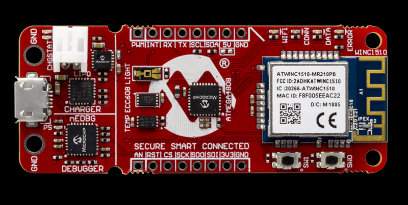
The board has a section with a USB port for charging a battery and debugging that looks like it is made to cut away. There are a number of LEDs and buttons along with a light sensor and a temperature sensor. It feels like the goal here was to pack as many Microchip parts onto a single dev board as possible. You’ll find the ATmega4808 as the main controller, an ATWINC1510 WiFi controller (a castellated module reminiscent of the ESP8266), the ATECC608A cryptographic co-processor, MCP73871 LiPo charger, MIC33050 voltage regulator, and an MCP9808 temperature sensor. We can’t find much info about the “nEDBG Programmer/Debugger” chip. If you’ve used it on one of a handful of other dev board, let us know in the comments about off-board programming and other possible hacks.
Naturally, the board works with AVR Studio or MPLAB X IDE (Microchip bought Atmel, remember?). Of course, Atmel START or MPLAB Code Configurator can configure the devices, too. There’s also an AVR-IoT-branded website that lets you use Google cloud to connect your device for development. The headers along the top and bottom edges are compatible with MicroElektronika Click boards which will make anyone with a parts bin full of those happy.
Looks like you can pick up the Microchip boards now from the usual places. From reading what Microchip is saying, they would like to position this as the “IoT Arduino” — something someone without a lot of experience could pick up and use to pipe data into Google cloud. While that’s probably good, it isn’t that hard to use an ESP-device to do the same thing using the Arduino IDE and then you have a 32-bit processor and you can use whatever cloud vendor you want. Sure, it would be a little more work, so maybe that’s where this offering will appeal.
On the plus side, we really liked that there was a battery option with a charger already on board — it seems like that’s something we always have to add anyway. It may be buried in the documentation, but the user’s guide and the technical guide didn’t appear to have an average and maximum current draw specified, so battery life is an open question, although the video says “low power.”
Although it isn’t quite the same thing, we’ve seen ESP8266’s talk to Google servers for interfacing with Google Home. And while it is on the Amazon cloud, we’ve even seen a 6502 up there.


With boards like these I always wonder what niche they are supposed to fill.
Most iot products tbh.
My guess would be people who are more google cloud than hardware-hacker. You can talk to google scripts with an ESP8266 (barring an annoyance I never bothered to solve when google changes certs), but there’s no out-of-the-box support.
From the sounds of the article, this is something almost like codebender, with a web-based IDE programming the board. Probably very convenient for those who don’t have a clue how microcontrollers are programmed but want to do the IoT equivalent of blink some LEDs.
Thankfully, you can specify a root cert for WifiCliemtSecure these days to avoid said annoyance.
kind of like the “programmers” that couldn’t understand “C” needing training wheels languages?
As an actual ‘for-development-of-other-design’ dev board it can presumably make a case; what I find curious is how the power is distributed.
The ATWINC1510 specifically has 8MB of storage(vs 4 for the 1500) for extra system software capacity; and isn’t pitched as a competitor for any of the USB or PCIe NICs, so I have to wonder what the case for a discrete 8 bit microcontroller is. Seems like they should either have thrown a little extra GPIO and punch into their wifi part, and made it a single package replacement for all this; or provided a somewhat punchier microcontroller.
I wonder how seriously they intended the “Arduino IoT” push or was that just the authors take? (didn’t watch the video).
The ATmega4808 is not a lot different to the ATmega328 (used in most smaller Arduinos) It has 48kB FLASH instead of 32kB and 6kB or SRAM instead of 8kB. It wouldn’t be any trouble at all to write a hardware file for the Arduino IDE to work directly with this provided the ICSP pis are broken out to load a modified bootloader and a com port is wired to the hardware UART.
328(p) has 2k of sram, not 8.
Thank you for correcting me. And also thank you for doing so politely.
It says avr, but they stir up confusion by having it fully branded Microchip, along with the programming port being labeled in PIC fashion.
Along with being fairly expensive compared to what I’d estimate a ESP being along with a crypto coprocessor and li-ion charger IC AND being another IoT thing looking for a problem that doesn’t really exist.
It’s just one big identity crisis.
I totally agree. I can almost hear the board speaking. “Am I pretty? I am pretty, right? “
This board doesn’t seem to have ICSP programming port, USB is used instead for programming and debugging. Headers are for Click boards that Mikroelektronika makes. Those things are like shields for Arduino, containing different sensors, drivers, LEDs and other stuff.
All it seems to be lacking is 24 more bits.
I agree, a SAMD21 version would be cooler, especially at the same price.
What is stopping this from hooking it up to AWS IOT platform?
It can connect to AWS IOT also, check this https://github.com/MicrochipTech/Repurpose_AVR-IoT_WG_to_Connect_to_AWS
The nEDBG Programmer/Debugger is Atmel’s “solution” to the fact that their debugging protocols (including JTAG) are all proprietary and undocumented. Only their own tools (Atmel ICE, Dragon, etc. + maybe licensees that signed an NDA) support them.
So they offer this chip that translates the secret protocols into a slightly less proprietary serial port protocol (CMSIS-DAP + vendor-specific extensions) that is documented. E.g. OpenOCD (and thus gdb) can use it.
I have no idea why they have done it this way and what is the value of keeping these protocols closed today, but that is Atmel – they never had a problem with making their chips more expensive than competition while being less capable …
This debug chip has been introduced after the market was flooded with cheap dev boards with built-in debuggers (e.g. the ST’s Discovery boards) that didn’t need expensive dongles. I believe one of the first Atmel’s customers for this was actually Arduino, because they wanted to include debugging functionality to their boards since a long time.
There are many valid criticisms of this, but what I do love is the look of this board. Labeling each important part with it’s purpose, not just a designator and/or part number makes it cooler.
I agree. However the motive is to push other Microchip products such as the ATECC608, hence the extra effort to draw attention. You see the same in other vendor’s demo boards.
Microchip is doing a lot of interesting things with the Atmel catalog after they bought them out
EDBG (“Embedded Debugger”) is typically a cheap, USB-capable microcontroller, mainly used for programming and debugging via SWD, JTAG or the like. It often also implements a UART-connection to the main processor, sometimes also an SPI slave intefface. EDBG controllers can be found on several, if not all Atmel Xplained boards, they fully replace the expensive Atmel ICE on that boards. Like an ICE, the EDBG has a bootloader and can be updated via USB. The main differences to an ICE are obviously a hardwired connection to the target processor, and target support is limited to the debugging / programming interfaces of the connected target processor.
Now THAT’s a completely insane board!
The EDBG is a 32 bit ARM Cortex M0+ SAMD21E18A, with 256 KBytes Flash, 32 KByte SRAM, capable of running at 48 MHz at 1.2 V Core, 3.3 V I/O, needing not more than 7.3 mA at 3.3 V And it is only used to programm a lame 8 bit AVR ATmega4808-MFR, with 48 kBytes Flash, 6 kByte SAM, capable of running at 20 MHz – if supplied with AT LEAST 4.5 V, burning 8.5 mA at 5 V. At 3.3 V (as on the board), the safe operating area of the ATmega is more like 12 MHz. The SAM can run circles around the ATmega on that board, while using much less power.
What were they smoking when they designed that board?
Reminds me of the time when they used the ESP8266 as a mere „Wifi Shield“ for the arduino.
Kind of. The difference is, this one works out of the box with Google, and is immediately accessible from anywhere in the world without lifting a finger. Just set the wifi L/P and it working. It comes preloaded with a demo firmware.
I would need an ATSAMD5 to be the main microcontroller in order for this to be a viable option for me. Also a lower price point ..say $20-$25 USD would be better
Meh
Hi there! I have very serious problems with this board. Specifically with the WiFi connection.
I have connected it in two modems of different brands and I have only been able to test it using my cell phone as an access point.
I have tried in different ways without having satisfactory results.
I was reading the programming documentation of WINC1510C and I got to the topic of the “ScanRegion” section Asia = 14 North_America = 11
I don’t know if this has anything to do with my problem.
And I comment this because if I can see in the setup of my home Router that it does connect. But nothing else happens. They recently published some MQTT libraries but they won’t help me much if I have to use my cell phone as an intermediary for their application (it makes no sense)
I hope you can help me with this issue. Any guide will be welcome