Have you ever had one of those moments, when you’re rummaging through your spare parts heap, and have a rather bizarre project idea that you can’t quite get out of your head? You know, the ones that have no clear use, but simply demand to be born, of glass and steel and silicon?
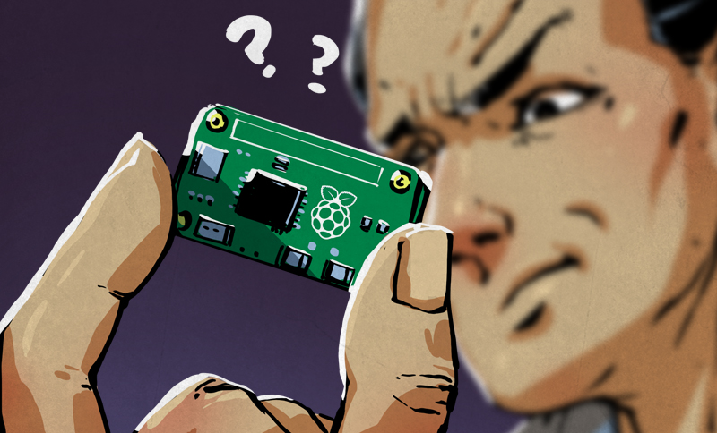
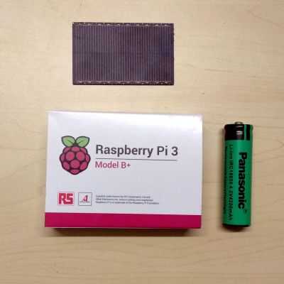
This time, the stubborn idea in question was sort of like a solar-rechargeable LED throwie, but instead of a blinking light, it has a fully cloud-accessible embedded Linux server in the form of a Raspberry Pi 3 Model B+. Your choice of embedded Linux board should work — I just happen to have a lot of these due to a shipping error.
There were two main challenges here: First, it would have to combine the smallest practical combination of solar panel, power supply, and Li-ion cell that could run the Raspberry Pi. Second, we’ll need to remotely activate and access the Pi regardless of where it is, as well as be able to connect it to WiFi without direct physical access. In this article we’ll be dealing with the first set of problems — stay tuned for the rest.
Sipping on Solar
I approached the first challenge from the standpoint that the Raspberry Pi doesn’t need to be on all that often. An ESP8266 (Wemos D1 Mini) running NodeMCU can provide battery management, and receive commands over MQTT to activate it, while staying in deep sleep mode most of the time. This consumes very little power, allowing a small 5 volt solar module to trickle-charge a lithium ion cell large enough to power the server for a few hours of run time.
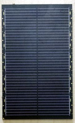
The solar modules are worth a quick mention. They are the LR0GC02 (PDF) from Sharp, designed to trickle charge a variety of mobile electronics. Unlike a lot of modules out there, they are both extremely well encapsulated and very thin (about 1mm). They also come with detailed specifications. A single 300mW module is enough for this project, but I used three in parallel during development to speed up various tests. This tiny solar power module would also have been an interesting choice.
Managing the power from these modules is where things get a little hairy. We have a 4-5V power source charging a Li-ion cell that has a nominal output voltage of 3.7V. Then we have an ESP8266 module, which runs at 3.3V but can accept higher through an integrated linear regulator, as long as you watch the dropout voltage. Finally, we need a 5V output that can be easily toggled to power the Raspberry Pi. Also it would be nice to have a 12V line for future expansion.
Magnificence of Modern Modules
Thankfully that all sounds worse than it actually is, and there are some very common modules that will sort this out for us:
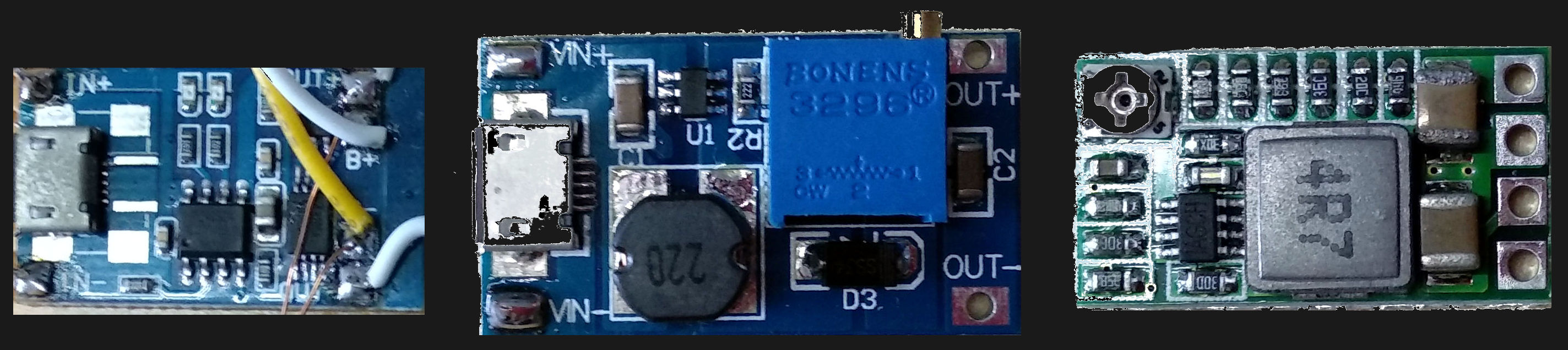
The first stage is a USB lithium ion cell charging module. These accept the ~5 V output from our solar panels, and will safely charge our cell. The output of the module is whatever the Li-ion cell voltage is.
Next in line, I added a DC-DC boost converter module set to output 12V. These modules are better than 90% efficient, accept a range of voltages, and will output a fixed voltage that is set by a trimpot. The 12V output is connected to the linear regulator on the ESP8266. This way, even if the cell voltage drops below around 3.7V, it will continue to function. This is critical as the ESP8266 monitors the Li-ion cell and switches the server on and off. If we were to connect its linear regulator directly to the cell output, it would shut down due to power loss while there was still quite a bit of usable power in the system. We do lose a bit of efficiency here, but the ESP8266 is off most of the time, so I can tolerate that.
The 12V output is then fed into a DC-DC buck converter to drop the voltage down to 5V for the Raspberry Pi. It’s important to use a buck converter with an enable pin, so we can control the output state using the ESP8266 later on. Otherwise you’ll need to add a MOSFET or similar to control the power output.
Responsible Battery Management
At this point, we have all the voltage levels we need, and charge control circuitry to prevent our Li-ion cell from engaging in spontaneous unplanned combustion. However, when lithium ion cells are discharged too far, they cannot be safely charged again. We need to monitor the cell and prevent it from rendering itself into an unusual paperweight.
The solution is quite straightforward: the ESP8266 has an analog to digital converter. It can only accept up to 3.3V, and our cell can supply more than this, so I used a couple of 100kΩ resistors set up as a voltage divider to drop the voltage – we don’t exactly need high precision here.
To start our control program, I set a timer to run the ESP8266 for 11 seconds before sleeping for 10 minutes, this is plenty of time for the chip to check for commands online. Then, if the cell voltage is below 3.4 volts, it will immediately sleep for 16 minutes instead.
function checkvolt()
x = adc.read(0)
print (x)
	if x < 528 then
		print("low battery, sleeping longer")
		node.dsleep(960000000)
	end
end

checkvolt()

function sleeping()
    node.dsleep(600000000)
end

tmr.alarm(0,11000,0,sleeping)
Some rough calculations suggest that the module will consume an average of around 1.5 mA normally, and around 0.2mA if the cell voltage is low. In reality there will be some current consumed by all the parts even while the system sleeps. I’m told that the sun shines at least once every month or so (I’ll check at some point), and the cell should not have trouble maintaining charge. In any case, if the former assumption is wrong, I have bigger problems to deal with.
Regulating the Voltage Regulator
Finally, we need to be able to control the output of 5V from the last voltage regulator. While I purchased a module that had an ‘enable’ pin available, there was no documentation as to how it worked, and the exact chip used in my module was unclear. Looking at datasheets for a few ICs from different DC-DC converters, it looked like it was probably an active-high enable pin that was pulled up with a resistor on the module.
I tried pulling it back down with a 50kΩ resistor, and the voltage output dropped to zero. Supplying 3.3 volts from one of the GPIO pins of the ESP8266 triggered the enable pin, and it output 5V again.
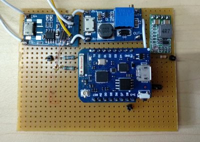
I discharged the cell a little, then left it running in the sun for an hour – it recharged a bit as expected, prompting the requisite maniacal laughter. Power stages… complete!
Where’s the Linux?
 It’s small, it’s solar powered, but other than lounging about in the sun, it doesn’t really do anything yet. Most computing hardware requires software and obviously this is no exception — so how do we make this into a lean, green, Linux machine?
In the next article, we’ll cover how to control this system via MQTT, set up remote configuration (for example if I need to change my WiFi password), and set up a reverse-SSH tunnel so we can connect to the Raspberry Pi without having to reconfigure our network to accommodate it.
The irony that my servers now get more sun than I do is not lost on me. I live near the equator though, and sunbathing for extended periods is an activity reserved for tourists – one that they normally learn to avoid pretty quickly!


hmmm its a bit tricky when the units are using same letter different caps
I thought the same :)
Small caps or listing in watts when title styles conflict avoids ambiguity. Though context should tell you that most hobbyists don’t have MWs of solar power at their disposal.
It’s always strange when people want 100mbit/s internet connections. I strongly prefer some Mbit/s
More importantly, a linux board that eats little power 74mA started at $4
https://www.indiegogo.com/projects/vocore2-4-coin-sized-linux-computer-with-wifi#/
https://www.acmesystems.it//arietta
https://www.acmesystems.it/power_consumption
Hi Lucas thanks for the tip, have always liked the SAM series.
” I just happen to have a lot of these due to a shipping error.”
But that, my friends, is another story!
Shipping error? What, they dropped of a truck?
I thought it would be boring to mention, but since you asked… effectively I ordered a fair number of these along with a few thousand dollars of other components needed for a project.
The “shipping error” in question was that the supplier only delivered the Raspberry Pi boards, folded their company, and vanished with the rest of the order. An international lawsuit would have cost me much more than the value of the parts, so rather than double down on the expense and time, I canceled the project and moved on to other things (there are always a dozen waiting it seems). It’s unfortunate, but also occasionally the cost of doing business. On the bright side, I’m exceedingly well stocked with Raspberry Pi boards.
I would have written up the tale, but the suppliers in question don’t deserve to be remembered. A warning would have been fruitless, as they no longer operate. Overall my suppliers are fantastic and all this was a blip on the radar.
Sorry to hear of the unfortune.
#metoo
I was gonna say “psh! Rpi is HARDLY throwy pricing!”
But then this.
“I can do that with a…”
You can power a city with 300 MW – i think you want to write 300 mW.
I think general fontage of the site causes issue here,
Though anyone confusing the two wouldn’t be reading this
Yes, to be clear it’s definitely mW. Otherwise I’d have a lot to explain.
Of course: Where did you get so many solar panels :-) And where did you put them (mount them) :-)
I’ve changed the article title from 300mW to 0.3W so that the all-caps title is clearer. Just making a note here so that the comments make sense to future readers.
Back in the olden days this would never have happened, because hackaday didn’t allow any capital letters. If you wanted to write megawatts it would come out as “mw”.
Ah ‘mw’ the SI unit of feline frustration.
Lithium – > Li-ion.
While metallic lithium based batteries exist, they are often not rechargeable.
Battery – > cell.
This is a 3.7V Li-ion cell.
Thanks, I missed that, and battery vs. cell is usually one of the things I check. Hold on, I’ll fix that for you.
I clicked on this thinking Wow . What linux server requires 300 MegaWatts of power (300 MW) as I am in the power industry. Anyway, thanks for the read.
Funny story, if you use inspect source you see that it is actually written as 300mW. Hackaday uses a CSS ‘text-transform: uppercase’ on their h1 and h2 elements.
I’m pretty sure they used to use a ‘text-transform: lowercase’ on all of the comments.
yes, headings used to be all lowercase as well. See the archives… https://web.archive.org/web/20090311002702/http://hackaday.com:80/
Not just headings – comments were all lowercased as well, so you couldn’t comment something like “:D”
300MW ….. Bitcoin mining?
Google?
I’d hate to think we needed a googlewatt….
Could have simply spell it out as “milliwatt” and avoid the confusion…
Or 0.3 W
I doubt even a single one of the comments about it was based on “confusion.” ;)
I am more interested in the tiny 300MW solar cell in that panel size.
I’m pretty sure 75% of people who comment on hackaday articles only click on the articles to flex their pedantry
Guilty as charged!
B^)
Also guilty.
Since I’m allergic to putting my homestead data aq and control on the internet, I’d change it to talk to one of my always-on servers instead…(which are pies and odroids as NAS and data aq/control)
But then, the whole place is on solar anyway (~ 6kw array when the sun shines), so what this would save is a piece of wire N feet long…with a few strands for data and power.
It’s cool anyway. My kind of toys.
Not switched over to the Tokamak yet, then?
Ain’t the ADC of a esp8266 only up to 1.1V?
Correct! No idea if the board he is using already has a voltage divider set up tho..
That’s correct, this board has an integrated voltage divider on it. I’ve used it so often I’ve forgotten it was there.
I think that’s on the chip pin. On a dev board, it’s devided by two resistors to ‘about’ 3.3v analog input on the boards’ pin…
That is an interesting question.
On the external pin it is 1.1v
But if you ask the kernal to measure its own supply power it can steady measure up to 5v.
Yes, the SoC can handle 5v.
I’m exited. Great idea.
Screen, router, raspberry, keyboard and meybe small lamp for seeing a keyboard ;)
365 day per year. Is possible?
I have been down the same road with my background radiation monitor using an ESP8266. I started off with a small panel like this that is feeding into one of those Li-Ion charger boards, changed the charge rate resistor to match the output of the panel and was getting a few weeks or so out of it before the daylight could not keep up over last winter. I recently switched to a 12v panel and a 7805 regulator to feed the Li-Ion charger board and it is working much better. Again though, I have pulled it apart to change the 18650 cells because either I have a current draw issue or the cells are bad, possibly even diminished battery capacity due to the low temperatures here now that fall has arrived. The whole thing wakes from a deep sleep every 10 minutes, takes a radiation measurement, reads the temperature/humidity/pressure and solar/battery voltages and then before going to deep sleep fires everything off to my MQTT server. My MQTT server is a nano-pi neo NAS setup and also has node-red installed, that takes care of sending the www data to radmon.org and wunderground for the world to see.
Interesting project you have and I will follow along!
I’ve used similar setups, the approach works very well! Luckily I’m near the equator and have to deal more with waterproofing than winter, and the angle of the sun doesn’t change as much over the year. Its quite convenient!
You’d probably do much better using a DC-DC convertor, to change the 12V to 5V. A 7805 just converts the unwanted voltage into heat, hence the heatsink. A convertor would convert it into extra amps. Your batteries would charge at pretty much double the rate.
You can get DC-DC modules online for a dollar or two, not much more than the 7805.
If you wanted yet more efficiency from the solar, an MPPT controller would do that. It changes it’s input impedance to draw the optimum combination of voltage and current from the panels, giving most power. Since solar panels often end up charging batteries, there are combo circuits that will do MPPT and manage 18650s, providing a simple steady voltage output for your use. You can buy these ready-made boards online from China, Amazon, Ebay etc have loads of them, among other suppliers. They’re not expensive.
I used a cheap <$1 dc to dc converter at first and it took some current from the panel to actually start the converter up when I was watching the daily graphs. I was using the logic that more time charging even at a lower current rate would be very similar. Obviously I should run two of them side by side to make a more scientific comparison!
At some point I will go looking for a MPTT board for a better solution but had the 7805 on hand.
>solar-rechargeable LED throwie
I knew you people could not just put the idea of these things to death.
>Managing the power from these modules is where things get a little hairy. We have a 4-5V power source charging a lithium cell that has a nominal output voltage of 3.7V
That’s not an issue. The current of a PV cell diminishes to zero at full voltage, and a Li-ion battery can be charged to 4.3 Volts. You also need to add a diode in series with the PV cell to prevent backwards discharge when the cell is dark, which means you already lose about 0.7 Volts off the top anyhow, leaving you with just enough to top up the battery.
According to the data sheet, the maximum open circuit voltage is 5.7 V at a wide range of light input, so all you really need is two silicon diodes in series or a zener directly to the battery.
It’s technically possible to overcharge the battery, but it will take literally forever at microamp currents. Still, if you’re worried, use NiMH cells instead.
I totally agree, and was coming here to say this (or something similar)
The charging scheme in this article is over complicated. There is a loss of efficiency at each stage too.
I was thinking of an LDO instead of a diode, but I’m not certain how it would behave when the cell voltage drops below the battery voltage, so a diode may be smarter.
The almost EOL i.MX23 and i.MX28 include a Li-ion charger and need no external DC-DC converter to run from up to 5.25V, but I don’t know if they continue charging while the ARM core is off. They are still fine for many tasks that don’t need lots of computing power.
It’s already been done. Even built a hat for the Pi-Zero https://hackaday.io/project/26272-pi0w-solar-hat It has power regulation and a fuel gauge. The problem is the Pi is a power hog, To effectively power a Pi on a long term basis it will require a very large solar panel and an absurdly large battery. Sure for a day or two, it will run on 18650 battery and a 3W solar panel but…. It’s so cut down, power wise forget any extras like a camera. I ran a Pi-Zero with camera on a 20w panel 10Amh lithuim battery and it would only last three days at best.
Glad to hear you also got the Raspberry Pi working with a solar panel and battery. It is indeed a power hog and 3 days run time is not bad!
I’ve taken a different approach here, in that I don’t try to power the Raspberry Pi on a continual basis. Instead, I provide a low-power control system on the ESP8266 that can be powered indefinitely with a modest solar panel and battery. This low-power system activates the Pi only when needed. It’s not designed to be used for more than a couple of hours at a time.
At this stage our projects are conceptually very similar. I’ll be following up with a second article shortly where our projects diverge quite a bit — I hope you will find it useful!
The updates are working so far — I can remotely turn the Pi on and off from the cloud — but I’m still stress testing it to see how reliable it is, messing with some scripts, and so on. The last thing I want to do is install this in a remote place then have to go back in a week to fix it.
the tp4056 has over-discharge protection, although it cuts-out at 2.4v at which point your battery is probably toast. no idea why they set it that low, but if you’re willing to risk it you can remove some esp8266 code/circuitry
That is unusual! Also, I suspect the cutoff feature is not implemented on my board. I checked the resistance between the pads where the cell is connected and the output pads on the module, and it was ~0 ohms.
I’m not completely certain though as I didn’t investigate further. Caveat emptor!
Some boards don’t have that cut-off incorporated. I forget the part numbers of the devices but there should be two extra pieces of silicon on the boards that have that protection, one is a FET package and the other is the voltage monitor. They are easy to spot on the shopping sites, both boards are pretty much the same size and both will show up in a search for the tp4056
It is possible to see the full code?
Thanks
Of course. Stay tuned for the follow up article.
Pi takes about 2W (let’s be pessimistic)
Sun only shines 1/3 of the day, let’s say 1/4
So to gather that amount of energy I’d need an 8 Watt solar panel.
To store it, I’d need 2W over 24hrs (being pessimistic again.) = 48 Wh, let’s say 50Wh Battery.
If you’re close to the equator it’s probably not such an issue, but for those of us in more seasonal climates, one other consideration for Li-Ion batteries is temperature. Charging one below or even near 0 degrees Celsius causes lithium plating on the anode similar to the effect of over charging. This has the potential for catastrophic failure over time. It’s worth adding a temperature sensor and charge enable to the ESP to allow it to shut off charging under such conditions – a not uncommon in the UK, frosty, but clear winter’s morning. Alternately use a different battery chemistry (NiMH or SLA) or keep it well away from flammable structures!
Is there a pinout diagram you have for this? I have most of the parts but am unsure if I am getting this put together correctly