When life hands you lemons, lemonade ends up being your drink of choice. When life hands you non-standard components, however, you’ve got little choice but to create your own standard to use them. Drinking lemonade in such a situation is left to your discretion.
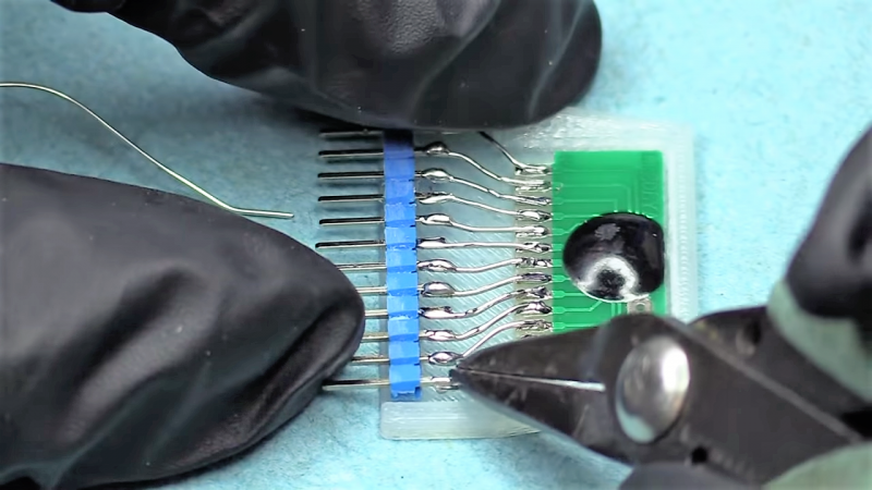
The little audio record and playback modules [Fran Blanche] scored from eBay for a buck a piece are a good example. These widgets are chip-on-board devices that probably came from some toy manufacturer and can record and playback 20 seconds of audio with just a little external circuitry. [Fran] wants to record different clips on a bunch of these, and pictured using the card-edge connector provided to plug them the recording circuit. But the pad spacing didn’t fit any connector she could find, so she came up with her own. The module and a standard 0.1″ (2.54 mm) pitch header are both glued into a 3D-printed case, and the board is connected to the header by bonding wires. It makes a nice module that’s easily plugged in for recording, and as [Fran] points out, it’s pretty adorable to boot. Check it out in the video below.
Sure, the same thing could have been accomplished with a custom PCB breaking out the module’s pins to a standard card-edge connector. But [Fran] knows a thing or two about ordering PCBs, and our guess is she wanted to get this done with what was on hand rather than wait for weeks. There’s something to be said for semi-instant gratification, after all. And lemonade.


I bought these exact modules and had the same problem! Thank you for sharing!!!
Mike’s lemonade?
Proof you can make an alcoholic beverage from anything.
Twenty seconds of audio would be enough time for quotes or lines from movies. I’m betting you are building a sequencer.
I don’t know how you keyed the cartridge to allow only one way to plug it in.
If you added one more row you could plug the row on the header and cut one of the corresponding pins on the cartridge. A design idea that comes after you’ve made a thousand already. (Sorry)
You could do the keying with the plastic cartridge and a corresponding socket for it. Like a SATA connector, sort of.
Half the comments on the Youtube video are suggesting keying. Yup it would be a good idea.
Mike’s hard lemonade – I only wish i could get it here. My store bought drink of choice when i’m in the states.
In the absence of a 3D printer dousing a whole package in hot glue works almost as well. The downside is it looks terrible.
I’ve done this before. To make things a bit more presentable, you can always cut and shave the glue till it resembles a nicer shape.
you can use tic-tac packages and a few fixing dots of hot glue. even you can shove an oled screen inside.
If you did make the header a double-row of pins (as suggested in an earlier comment), just wire the pins on the 2nd row of the mating socket in reverse (you would not need to wire the 2nd row in the module itself…let the socket do the hard work). That way, even though you use twice as many pins, it’l be right no matter which way you turn the module as you plug it in.
“USB C” thinking.
Not always possible, since 5V one way round might be 0V the other, so if you plug it the wrong way, you end up reversing the voltage supply. You can cope with that using diodes, but they’re not suitable for everything, some of the pins are analogue, and might object to being connected to the wrong thing.
If you’re gonna re-do the connector, the simplest thing is just to key it, with a missing pin.
Greenaum:
I probably did not explain exactly what I meant in a clear enough manner.
I’ll use 4 lines labeled “A”, “B”, “C”, & “D” (in the original connector, in that specific order) as a simple example:
With a single row, there is only one way to plug it in that is correct & you *must* insert the plug in that way, else the magic smoke might escape:
ABCD
If you expand this to a double row, then no matter which way the plug is inserted, it will always be correct:
ABCD
DCBA
Hopefully that clears up what I meant . . .
Mark J Culross
KD5RXT
Suspending the normal avoidance toward exhibiting bad form by replying to my own post for a moment, I forgot to re-emphasize that you’ll need both a double row of pins on the module’s plug, as well as a double row of sockets on the host board’s mating connector. For simplicity, only one of the two rows of pins on the module needs to be connected, but both rows of sockets on the host will need to be wired appropriately (again, let the socket take care of the hard part, saving the pain of any extra soldering on the module). As long as you plug (in this case) all 8 pins in, it does not matter which way the plug is rotated. Hope that the original intent is even clearer now. MJC
Interesting
I used this method while waiting for SOIC2DIP boards to arrive, works very well on a whole variety of unusual packages, and also on usual but not-just-what-i-need-now ones.
Having alignment pin would be nice to not plug it in wrong way.
You can get these modules in various configurations up to 120seconds recording, pretty fun. Some have all the components as well as battery contacts built-in, all that for 2$.
Don’t see how keying, in this case, is of such great importance. The blob on board is a great landmark. If this was for production work, certainly it would be better to find a proper socket, or make breakout boards, rather than hand solder all those pins and wires
https://www.ebay.com/p/Isd1820-Sound-Voice-Recording-Playback-Module-With-Mini-Audio-Speakers-I5p4/1681179860?iid=112621949097 is for nearly the same price and has normal pins.
The original one was probably intended to just solder it into a slot of a pericardium PCB. What pitch does it have any way?
not “pericardium” but “perpendicular” I hate auto un-correct.
Very cool, but wow! A Chinese product that includes in its description: “Can be used as a propaganda module.”
Maybe I can put some around the house and propagandize the family into doing their chores. No? Off to the gulag!
You’re right, your proposed module is absolutely better suited for DIY purposes, but too boring for Show Business !
Super Cool Youtube hacker prefers to impress us with her skills at some rather obvious header soldering, applied to her “Super Cute *Done It Herself* Mini Cartridge” (with its mandatory 3D printed enclosure) while telling us almost nothing about her So Gorgeous Manhattan-style host circuit on a perfboard which it is plugged into….
Definitely much fancier and good looking than all those regressive ugly breadboards :)