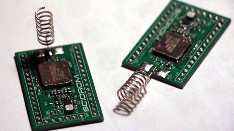
[Mare] has a visual guide and simple instructions for making DIY mini helical 868 MHz antennas for LoRa applications. 868 MHz is a license-free band in Europe, and this method yields a perfectly serviceable antenna that’s useful where space is constrained.
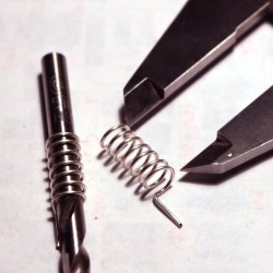
The process is simple and well-documented, but as usual with antenna design it requires attention to detail. Wire for the antenna is silver-plated copper, salvaged from the core of RG214U coaxial cable. After straightening, the wire is wound tightly around a 5 mm core. 7 turns are each carefully spaced 2 mm apart. After that, it’s just a matter of measuring and bending the end for soldering to the wireless device in question. [Mare] has used this method for wireless LoRa sensors in space-constrained designs, and it also has the benefit of lowering part costs since it can be made and tested in-house.
Antennas have of course been made from far stranger things than salvaged wire; one of our favorites is this Yagi antenna made from segments of measuring tape.


Can someone explain why a helical antenna is in this case better than a straight antenna? Are there disadvantages to use a helical antenna?
It’s shorter and depending on the type of helical antenna, it’s radiation pattern is different to a straight one. It also has a different impedance in comparison to a straight antenna…
Disadvantage is more complicated manufacturing. Uneven spacing of the turns will result in more resonant frequencies, which unless specifically desired should be avoided.
This type of helical antenna will have lower gain than a straight 1/4 wave antenna. The advantage is that it’s compact.
And at those frequencies, I don’t get the need for a shorter antenna. Antennas are so short that even lengthened they won’t stick out much, so you might as well go for a !onger antenna, which would give gain.
At 144MHz, a quarter wavelength is around 18 Inches, and on a portable, that might get in the way, so antennas are often helically wound to make them shorter, despite the lower efficiency.
But higher up, a quarter wavelength can get pretty small, no need to make them shorter.
Originally, I thought this was about a gain antenna, directional and the coil being part of that, but now I’m not sure.
MIchael
the ‘diy’ tag really helps xD
Rather than having the calipers out, would probably be easier to just 3d print a jig for it.
Shoo. It’s several turns of coiled wire, no need to 3D anything. Save the 3D printed jigs for 3D fractal antennas.
To be fair there is a requirement to get the turn spacing right and at these frequencies a little error goes a long way. I wouldn’t dismiss either approach until I had thoroughly tried both.
Another possibility for evenly spacing is to wind three or four pieces of wire at a time, so they space themselves when tightly wound. You have to unscrew the result but that’s not too bad. It’s been my experience that you’ll get a more uniform coil if you wind it tightly (either alone or with other wires) and then stretch it to the separation you want, rather than trying to wind it to the separation you want.
I wind over a mandrel on my lathe, using the threading settings. I made a little tool – a piece of wood with a guide slot in the end, and a separate rod clamped in the toolholder for the spool of wire.
This beats every other coil winding method I’ve ever used, including purpose-built machines.
Lately I’ve been working the other end of the spectrum and winding 4″ diameter coils 6″ long…spaced. Easily.
I got a hack transfer of $31,000 from kloviaclinks com tools and they are legit.
I’m just going to leave this here so someone might actually create it: https://www.reddit.com/r/RTLSDR/comments/9s6l6t/just_discovered_the_macgyver_remake_was_not/
Something I’ve always wondered about small data radios like this (I’m thinking of all of them, LoRA, Bluetooth, Zigbee, Hoperf, wifi, etc….)
Do you ever bother to measure SWR? If so then how? I’m thinking soldering on some coax, putting connectors on everything, etc.. in order to hook up a meter wouldn’t work as that whole setup would have more effect than the antenna itself. But.. I don’t know that.
How much does it matter? Obviously it would have the same effect on signal strength as it would on any other radio device but can it fry the finals like it can in a CB or ham radio? Or are they hardened enough and the power low enough that they could transmit into an open circuit or into a short all day long without breaking a sweat?
Is it even possible to account for SWR? Or are these tiny antennas and such high frequencies so fussy anyway that they are liable to completely change impedance every time a cricket farts 3 houses away thus making tuning pointless?
Most of them transmit at low enough power levels that reflection can’t damage them. Precise tuning is hard, but when you’re not concerned about heating up the finals, precise tuning isn’t very important. A 50 ohm transmitter can feed an antenna anywhere from 19 ohms to 133 ohms with less than 1dB of reflection loss. Rough numerical modeling can get you into a ballpark that big pretty easily.
Technically not a helical antenna. More accurately maybe a inductively top-loaded vertical antenna? A helical has special properties like circular polarization. The sizing of this antenna is incorrect to be helical.
maybe monopole antenna rather than vertical since I don’t actually know his orientation.
You’re describing an axial-mode helical antenna, where the circumference of a turn is close to one wavelength. This is a normal-mode helical antenna, which acts as a monopole with a distributed inductive load.
Yup. For those that want to know more here’s a plot of the types of helical antenna modes as turn circumference vs turn spacing (in wavelengths): http://erewhon.superkuh.com/library/Electromagnetics/helical-antenna-axial-modes_vs_turn-circumference_vs_spacing.png
Normal mode helicals like this are electrically short and so capacitive in behavior. Another way of looking at it is that the inductance of the winding mitigates this.
That’s a really interesting graphic!
Thanks for linking it.
You mention using the core from an “RG214U coaxial cable”.
A simple Google search finds that RG214U coaxial cable has a 7-strand Ag plated copper wire.
Where did you get the “RG214U coaxial cable” with a solid core, you used in this project ?
Hi,
Only single thread from 7-strand Ag plated copper wire was used. One length of core conductor is for 7 antennae.
Where can I find the formulas to adapt these kind of antennas to other frequencies?
3D printed template for the wire: https://www.thingiverse.com/thing:4941361
Yay! 3D prints for jigs for things like this are awesome.
This (https://www.thingiverse.com/thing:367500) is the best 5.8 GHz antenna I own, although if I were doing it again, some of the other frames look sturdier…