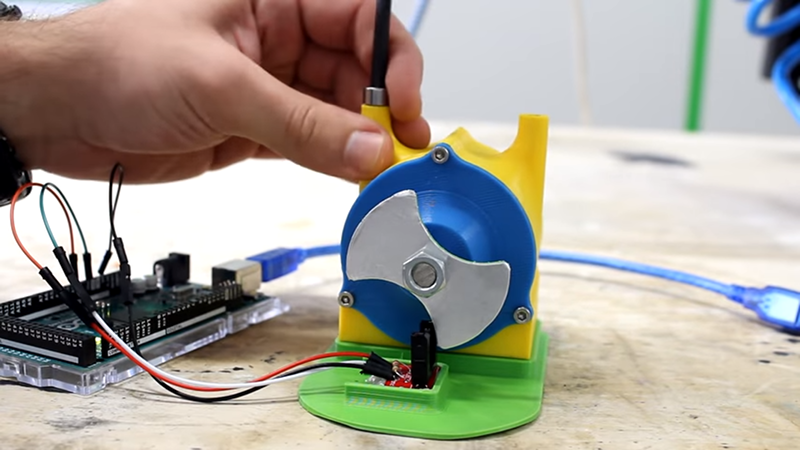
[Integza] built a Tesla turbine and wanted to know how fast it was spinning. However, he didn’t have a tachometer, and didn’t want to buy one. After a false start of trying to analyze the audio to measure the speed, he decided to use a tried-and-true method. Let the wheel break an infrared (IR) optointerruptor and count the spokes of the wheel as they go by. If you know the spacing between the spokes, you can compute the speed. There was only one problem: it didn’t work.
Turns out, PLA is at least somewhat transparent to IR. Knowing that it was a simple matter to fix some tape to the wheel that would block IR and that made things work much better. If you missed the video where he built the turbine, you might want to watch it first.
The results were good. Thanks to the Internet, [Integza] was able to appropriate some code from a nine-year-old Ukranian and use it as a base. With breath power he got a pretty good spin going, but with an air compressor, he handily broke 10,000 RPM.
We were surprised the audio method didn’t work out. We know big companies spend money with other companies to listen to compressors run and decide if they are about to fail. We suspect some audio processing through GNU Radio or some other DSP software could have recovered the actual signal, but we don’t know that.
If you haven’t seen a Tesla turbine before, it uses no blades and is very efficient. They may not have blades, but they can have hard drive platters.


This is a very weak post and it pisses me off that it is on HaD.
Im not dissing the project or the individuals learning. I am pissed off with the lack of technical information and the fact that its here on HaD.
Keep HaD technical do not dumb it down.
Really? The fact that PLA is transparent to IR, and thus won’t work with a number of beam-break sensors, isn’t technically interesting? I thought it was a useful nugget.
Another fun fact – smartphone cameras can see IR. You can point a remote control at a smartphone camera and press a button on the remote and see the IR led flashing on the smartphone screen.
You can also use the same technique to see if the emitter in a photo-interrupter is working.
I’ve found with the newer models they seem to filter out the IR and are no longer any good as an IR “display” :(
The older ones I have work great though
Prusa requires that the extruder be printed in black PET-G, because other colours mess with the IR laser filament sensor.
Try black PLA.
Nope. Black PLA is transparent to IR too, at least when it’s 0.8 mm thick. That one bit me hard one day when I though a black PLA printed sensor package would block all ambient light. I resorted to aluminum foil too.
It´s a fail. The right way is to use a neural network on a Jetson TX2 and upload the results in the cloud. From there it´s pretty trivial.
Of course it’s a fail – they should have used multiple Beowulf clusters made with Raspberry Pi’s, linked peer-to-peer over the internet, at least a dozen of them; or maybe rent some time on a crypto-mining rig to crack the problem properly…
Talking 2020, I think they should upload the experiment setup to the ISS to prove that gravity did not interfere with the experiment.
Multiple TPUs with high-end Xeon PC is also needed so we can transform from the state of neither confirming or denying the results to the state of fully knowing.
Hail Hydra
So the guy cant solder.
And 3D prints high rpm parts that can fly to pieces by centrifugal forces.
But nice blowjob.
He does know how to make a damn good video.
yep, I just watched a few and they weren’t bad – he clearly puts a lot of work into the video. However, I’m not going to send them to the kids due to the languange in some of them…
When I heard the thing hit 10K RPM I was kind of wondering how 3D printed parts would old up. Hopefully the pieces are made like plywood but still I wonder how consistent the material deposition is from a 3D printer. Interesting project.
This is an age old problem.
There are too many other sources of IR in the environment and sifting a signal from the background noise can be a challenge.
An opto-interrupter is not a digital switch. It’s an analog device. Sure you can set a threshold and use it as a “go/no go” sensor and it will work … for a while. But over time the receivers sensitivity and gain will change and your threshold will no longer be suitable.
The old analog solution was to CW modulate the transmitter. The receiver then went through a band pass filter, AM demodulation and then level detection. This way receiver gain and sensitivity was was fan less an issue. Also if you choose a modulation frequency that is far away from noise then it works well.
The good news is that there is a digital solution where the noise actually helps. The noise is like a varying bias which allows you to connect the receiver to a digital GPIO as long as your modulation frequency is high enough to get away from the noise.
With the diode (output) off test the state of the receiver (input) is the state is wrong then skip this test period.
If the state is right then change the output (diode on) and look for a change in the input in a very small time window. If it transitions then increase an index number and if doesn’t transition then decrease the number. Use a threshold with this number to trigger action.
You can also use averaging. It’s not unusual to average 1000 input samples when you have a high noise source like 60/50 Hz mains – think heater.
If your application has minimal latency demands then use an analog input instead,and lots of with averaging.
What I don’t understand is why he didn’t just feed the analog from the opto-interrupter to the audio input and use audacity…… no noise issues and no code
I don’t think audacity would cover it.
Here’s an old example that I had to deal with –
https://cdn.hackaday.io/images/6736761425517931934.png
The horizontal bars are noise.
If you squint a bit you may notice that jagged edges in the top half are two sine waves (actually two phases of one sine wave).
That sine wave is what I had to extract. The noise is obviously many times greater than the signal.
I achieved that with a digital GPIO, precise timing and lots of averaging to remove the noise. I only needed a phase reference though.
The VERTICAL bars are noise.
I’ve seen a TV remote where the IR LEDs were not exposed.
Ran into this same issue recently when trying to make a simple filament runout sensor. Basically all PLA is transparent in the IR, no matter what color it is. Here are some graphs that show the IR absorption spectra.
https://www.researchgate.net/figure/Fourier-transform-infrared-spectra-of-PLA-A-Ag-PLA-NCs-at-8-B-16-C-32-D-wt_fig4_46382345
https://www.researchgate.net/figure/Fourier-transform-infrared-FTIR-spectra-of-polylactic-acid-PLA-and-the-PLA-sisal_fig3_233980697
I had an idea to use the refraction of the filament to redirect the light away from the photodiode, however I couldn’t get it to work with the photointerruptor I had. Maybe if you used a seperate LED and photodiode instead of an integrated unit, you could arrange them properly to make this work.
It was fun to watch but it always weirds me out how the maker types tend to overcomplicate everything.
I made adhoc sensors using a pair of ir LED + phototransistor several times using reflectivity of the surface. One of them was even featured on HaD (look up Strobeshnik HDD clock). You can put a tiny piece of foil, or white paper, or use a white marker on your spinning part and this is enough. If the surface is already reflective, you’ll have to add something black. You can put a matte black mark directly on the axle and there’s no need to print a scary spinning hammer.