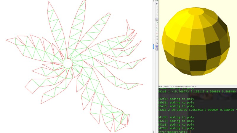
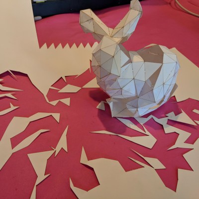
Some time ago, [Trammell Hudson] took a shot at creating a tool that unfolds 3D models in STL format and outputs a color-coded 2D pattern that can be cut out using a laser cutter. With a little bending and gluing, the 3D model can be re-created out of paper or cardboard.
 There are of course other and more full-featured tools for unfolding 3D models: Pepakura is used by many, but is not free and is Windows only. There is also a Blender extension called Paper Model that exists to export 3D shapes as paper models.
What’s interesting about [Trammell]’s project are the things he discovered while making it. The process of unfolding an STL may be conceptually simple, but the actual implementation is a bit tricky in ways that have little to do with number crunching.
For example, in a logical sense it doesn’t matter much where the software chooses to start the unfolding process, but in practice some start points yield much tighter groups of shapes that are easier to work with. Also, his software doesn’t optimize folding patterns, so sometimes the software will split a shape along a perfectly logical (but non-intuitive to a human) line and it can be difficult to figure out which pieces are supposed to attach where. The software remains in beta, but those who are interested can find it hosted on GitHub. It turns out that it’s actually quite challenging to turn a 3D model into an unfolded shape that still carries visual cues or resemblances to the original. Adding things like glue tabs in sensible places isn’t trivial, either.
Tools to unfold 3D models feature prominently in the prop-making world, and it’s only one of the several reasons an economical desktop cutter might be a useful addition to one’s workshop.


I thought, not having read through to the end that I might have to drop a hint that adding glue tabs would be nice…
> Adding things like glue tabs in sensible places isn’t trivial, either.
Ah! Yes. I really do need to add that hint:
Adding glue tabs is trivial. I figured this out more than three decades ago, not sure if it’s published, I don’t expect me to be the first to have found this, but it IS trivial.
To add glue tabs: Move along the edge and add a tab, no tab, tab, no tab. Alternate between tab and no tab. Always works. Not sure if my proof that this always works is mathematically sound enough that you can’t come up with a counter example, but you’re invited to try and find a counter example.
Your assumption here is that there are an even number of tabs + “no tabs”.
I think that only works in the case where each tab has exactly one corresponding “no tab” to stick to, and vice versa.
For instances where a “no tab” needs to accommodate two different tabs side by side, I don’t think it works any more.
Since each bonded edge has a mating edge, the number of edges is always even for any closed surface. Since STL files are supposed to be ‘water tight’ there will be no open edges.
No – that’s not always true. A non-tabbed edge could accept two tabbed edges.
I suppose adding tabs by themselves is trivial. However, unfolding in a way that leaves enough room for them in corners seem to me quite non-trivial. Am I worng?
Have you actually tried this plan on a complex model? Show me on the cutout above where these tabs would come from and tell me it’s still that trivial. Were all the test models for this algo just cubes by any chance?
There’s also the problem of dealing with faces that would interfere with one another when folded out flat.
This problem is still non-trivial in the 3D modelling world as well. with UV-mapping (unwrapping, projecting,..) for texturing.
I came for this; Maya has some pretty good UV unfolding tools. The “optimize” tool automatically lays out the selected UVs to match each polygon’s shape and surface area in 3d space as close as possible. Export the texture and print for a very handy way of making papercraft and such. I’ve done it before with lots of success.
Also works for quads and n-gons, which STL doesn’t seem to support–it’s a triangulated mess. When doing papercraft you would prefer to cut out a pentagon or w/e as a five-sided single shape, not three triangles which must be glued together. That effect is wrecking the unfold in the first image; the sphere is almost all quads, but it was unfolded as a mess of jagged triangles. That’s gonna be more than twice as much work as necessary, and won’t look nearly as clean. You’ll have to manually rebuild every flat face when you could just cut it from flatstock whole.
Use the original mesh exported as another polygonal format like obj instead (and can we talk about how weird it is that stl is a triangulated polygon format in the first place? What kind of CAD format for programming CNC machines has ever been polygonal?? Is there a story here?)
This somehow reminds me of UV Unwrapping in 3d modelling, and makes me wonder if its possible to have a texture file also be a paper-craft template at the same time.
That would provide me with excellent justification to keep my small car sized 11×17 color laser printer!
Yep! I’ve done it. Seems I need to document and post it. Maya has good tools for it but I bet blender will work almost as well once one gets over its horrible, horrible hotkeys.
Please do.
Would the sheet metal workbench from FreeCAD be usefull for this?