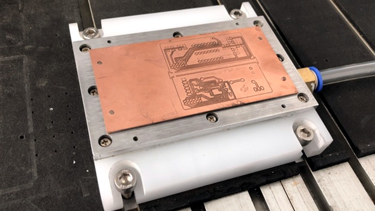
CNC milling a copper-clad board is an effective way to create a PCB by cutting away copper to form traces instead of etching it away chemically, and [loska] has improved that process further with his DIY PCB vacuum table. The small unit will accommodate a 100 x 80 mm board size, which was not chosen by accident. That’s the maximum board size that the free version of Eagle CAD will process.
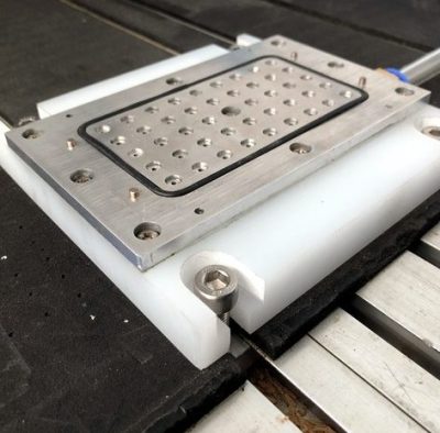
When it comes to milling PCBs, double-sided tape or toe clamps are easy solutions to holding down a board, but [loska]’s unit has purpose behind its added features. The rigid aluminum base and vacuum help ensure the board is pulled completely flat and held secure without any need for external fasteners or adhesives. It’s even liquid-proof, should cutting fluid be used during the process. Also, the four raised pegs provide a way to reliably make double-sided PCBs. By using a blank with holes to match the pegs, the board’s position can be precisely controlled, ensuring that the back side of the board is cut to match the front. Holes if required are drilled in a separate process by using a thin wasteboard.
Milling copper-clad boards is becoming more accessible every year; if you’re intrigued by the idea our own [Adil Malik] provided an excellent walkthrough of the workflow and requirements for milling instead of etching.


If you use a thin layer of particle board between the cob and the vacuum plate as a spoil board the air will go through it and pull the pcb down. Then you can drill with the same setup.
FWIW, you don’t need the o-ring. We build vacuum chucks for pcb and they are just a plate with a ton of little holes in it. Use paper or more pcb material to fill the unused areas.
Was going to be my suggestion too. The main benefit of CNC PCB production is the drilling of holes. It’s much faster to photo etch a board, but then you must drill the holes by hand. CNCing takes a long time and results in a lower quality result than photo etch, but saves time and annoyance when it comes to drilling.
That’s a real sucker..
A friend on mine runs a company supplying profession vacuum tables. They use machined sintered aluminium powder blocks as the porous contact surface. Really weird stuff as it’s hard to see the minute holes, just looks like alu.
Sorry. It was a ncet thought 10 years ago but sheesh i just placed an order for prototype boards in china and no way i can beat the price by milling. 5 different boards 1 was 4 layer various sizes one was 276mm_x_140mm, 10 of each all for 135$ including shipping. Yes i have a 5 axis cnc mill but not worth my time to mess with making boards.
Faster workflow has value, too. It may not be possible to compete on price for finished boards, but milling your own absolutely beats ordering from a fab house in China for turnaround time.
With good software you can go from design to board in a few minutes with a mill. For iterative protoyping that is hard to beat with any out of house manufacturing. You can go through several designs within a day instead of weeks.
Ever heard the phrase “measure twice, cut once”?
Where I work, it’s: build the board, hand to the engineer, he tests it, finds instability the sim didn’t show, hands me a new schematic, I build a new board, now because it works better coupling between miso and mosi is messing up communications, so I build a new one with more ground between them, someone makes a mistake and blows up a trace, I cut another… We’ve gone through six design iterations in a day, a number of times, and few of the iterations would have been avoided through more thought, because it’s brand-new silicon and we don’t know what it’ll do.
few minutes? that is going to be some long minutes
Can do the same with etching, and less noisy
I worked for 3 years in the North American Division Machining shop of one of if not the largest plastic supplier in the world.
We used vacuum tables almost exactly like this. Actually vacuum tables once you realize it’s just a very flat plate sealed off, really aren’t that complicated and can easily be made at any home shop. They are basically just plates with grooves for an O-ring seal and, in my case, 1/8 npt pipe thread brass set screws that opened the vacuum area to a sealed perimeter of gasket.
If you want to make one, the only expensive and complicated part is the vacuum pump. With a little bit of Googling there is a company who has come up with a way of using compressed air using a Venturi effect I think in the same way cold air guns separate hot and cold air to create pressurized and non-pressurized air, using a small aluminum block with a switch and internal stuff to create a stand-alone vacuum.
The only critical thing with a vacuum table is that it is absolutely dead flat. The best way would be to use steel and surface grind it, that would give you the flattest surface, but honestly the one I used daily for Plastics Machining of very expensive sheets of rare stuff I just surfaced with a normal fly cutter very very carefully. We had a Wikai oil filled vaccuum gauge on it, and special coiled steel wire filled clear tubing that was designed to work with vacuum systems that pulled the vacuum to the pump.
If you can cut your material with little pressure, and you want no obtrusions like clamps, it’s impossible to beat a vacuum table. If you get really creative, like I did, you can even make three-dimensional vacuum tables for very complex 5-axis parts. In a home shop, it should be doable if you know how to machine carefully.
I really like the sintered porous aluminum surface mentioned above. Kind of like high quality air and oil filters. That would theoretically give the most maximum sealing and pulling area.
Cool stuff!
Those venturi “no moving parts” units use a an absolutely absurd amount of air though. Something to keep in mind.
Flat and well supported is great, but z-level probing and on-the-fly adjustment work a treat too. I’ve getting great results with PCB’s from bCNC and the built in autolevel feature.
Personally I made a slightly curved 3D printed wasteboard to purposely introduce a slight curve in my PCB so I could ensure it was well supported across it’s entire body. It resists the vertical forces from the cutting bit well now and I get glean starts and stops on my traces. I can also drill without moving it and losing reference.
what kind of bit are you using ? i’m using a 30° 0.1mm v-shapped bit and the cuts are nice but way too thick…. like 0.5-0.6mm, instead of ~0.15mm (a 1mm track in CAD gives a 0.5mm track in reality) . I’m cutting at Z=-0.065mm (autoleveled with bCNC)
The LPKF we have at work has a sprung collet, so it glides across the surface of the material regardless of thickness. However (since you are unlikely to have that functionality) it also needs to have the cut width varied by raising or lowering the bit. Before I start, I take a test cut, and keep doing test cuts and slightly raising/lowering the bit until it is cutting approximately 0.12mm wide. I’m using a 60 degree carbide twist mill bit so it’s a bit more flexible on height.
There are manufactures who make these for larger force hold down applications such as milling of metals. It’s actually fairly neat but it does have limits you have to keep in mind as usual.
They are NOT inexpensive either to get the whole setup going.
https://www.datron.com/cnc-machine-products/vacuum-tables.php is one example.
Cool… one step close to the hacked out CriCut or similar system.