When reading textual communications, it can be difficult to accurately acertain emotional intent. Individual humans can be better or worse at this, with sometimes hilarious results when it goes wrong. Regardless, there’s nothing a human can do that a machine won’t eventually do better. For just this purpose, Tweetbot is here to emotionally react to Twitter so you don’t have to.
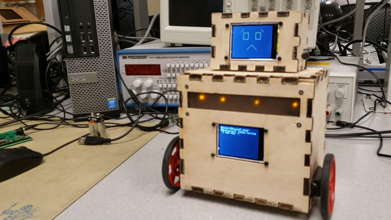
The ‘bot receives tweets over a bluetooth link, handled by a PIC32, which also displays them on a small TFT screen. The PIC then analyses the tweet for emotional content before sending the result to a second PIC32, which displays emotes on a second TFT screen, creating the robot’s face. Varying LEDs are also flashed depending on the emotion detected – green for positive emotions, yellow for sadness, and red for anger.
The final bot is capable of demonstrating 8 unique emotional states, far exceeding the typical Facebook commenter who can only express unbridled outrage. With the ‘bot packing displays, multiple microcontrollers, and even motor drives, we imagine the team learned a great deal in the development of the project.
The project was the product of [Bruce Land]’s ECE 4760 course, which has shown us plenty of great hacks in the past – Bike Sonar being one of our favorites. Video after the break.


The analysis for emotional content bit is handled on a Windows PC.
The remainder of the design looks somewhat wasteful as it could have been accomplished with a single ESP32 dev board rather than two PIC32s and a bluetooth board.
Hi Sweeney,
Thanks for your feedback. We used two pic32s as this was done for a microcontrollers class where we learned how to use pic32s and were required to use them for our final project as well as learn how to integrate additional components with pic32s.
Given the course was taught around them, I understand the use of the PIC32.
The ESP32 was outside your silabus, but is still a microcontroller (with integrated Bluetooth and WiFi), and very cheap (circa $5 for a complete board).
Looking at the schematic (in which you’ve forgotten to connect one PIC32 to the other, the only common connections seem to be power), it looks to me like you could have gotten away with a single processor. The LCD screens could have shared the clock and MOSI lines, and had independent CS pins (btw, your schematic looks wrong again, your CS pin is tied to that for the SD card socket on the display board). The LEDs could have been run from a single pin (WS2812 RGB LEDs need a single data pin for a chain of LEDs), and the speakers could have been driven by another single PWM pin with a simple R/C filter.