In these days of cheap microcontrollers, it is hard to remember there was a time when timing things took real circuitry. Even today, for some applications it is hard to beat the ubiquitous 555 timer IC. It is cheap, plentiful, and reliable. What’s interesting about the 555 is it isn’t so much a dedicated chip as a bunch of building blocks on a chip. You can wire those building blocks up in different ways to get different effects, and [learnelectronics] has a video showing the three major modes you typically see with the 555: astable, bistable, and monostable.
The 555 is really only a few comparators, a voltage divider, one or two transistors, a flip flop and an inverter. The idea is you use a capacitor to charge and the comparators can set or reset the flip flop in different ways. A reset input or the flip flop can turn on the transistor to discharge the capacitor.
The astable mode just generates a series of pulses. The bistable mode really just exposes the internal flip flop. The monostable reacts to an input by producing a fixed output pulse. Granted, you can make an Arduino or other microcontroller do all this but at the cost of complexity.
We’ve had plenty of 555 projects, some quite unique. We’ve also looked at the history of this venerable chip.


I feel the need to link to the 555 contest here from forever ago, including a 4th mode: “logic gate”.
https://hackaday.com/2011/08/05/building-a-computer-out-of-555-chips/
The trick with the 555, as Al says, is that it’s a few different functional modules, which are commonly used together, conveniently wrapped up in one chip.
These “modes” are just byproducts of hooking these modules up in this way or that way, and the key to the 555’s hacker popularity is that there are _far_ more than three interesting things you can do with the modules.
So yeah. I’m with you. A fourth, but also a fifth and a sixth and…
How many other chips are designed this way? As a toolkit rather than a monolithic function?
(I like the 4046 PLL which gives you a VCO and a trio of phase comparators, but that’s still limited compared to the 555.)
The output stage on the 555 is really handy, but sometimes I prefer a DIP8 ATTiny85 for more sophisticated timing and pulse generation sequences. Once programmed they need even fewer supporting components than the 555.
We need a new Workplace Safety poster…
“Days since a 555 incident on HaD: 0”
+1
Days since a ATMEGA chip was mentioned to do the job: 0
We used to use a 555 with a 741 or two to make sine generator. Just integrate twice.
What do you need the 555 for? Two op-amps make a sine generator by themselves.Also, integrating a square wave twice doesn’t yield a sine wave – only somewhat close to it.
Two integrating op-amps with a passive integrator in a loop does.
“The Three Phases of the 555” – I saw what you did there.
Just for fun: at digikey the 555 costs at minimum 0.35 euro per unit of 1. A pic10F200 costs 0.38 euro per unit of 1 so it’s almost the same cost. The complexity of surrounding components for the 555 is higher as the 10F200 has internal weak pull up resistors for the buttons and it doesn’t need a capacitor (maybe one for filtering the power pins). So the 10F200 pcb space can be more compact, especially with the smallest package. The 555 doesn’t need to be programmed so no tool chain is needed. For the PIC a PC with mplab, asm/c compiler, pickit programmer is needed. The 10F200 isn’t limited to simple flipflops etc and can be more complex and is reprogrammable. It isn’t fast though, at 4MHz and 1MHz instruction clock.
A cmos 555 will be a lot faster. At 0.67 euro per unit it’s almost twice as expensive. At that price point a PIC12F1572 at 0.60 euro has a 32MHz clock, 8MHz instruction clock and A/D converters, PWM and comparator that increases the functionality quite a bit further.
The time to program and test the PIC outweighs the cost advantage. Time is money.
You can buy them preprogrammed…. if you are manufacturing something, and one could argue that software is simpler to write than a 555 circuit is the design… there goes your time advantage if doing anything complex.
The main advantage of a 555 is if you are designing something to last > 20-30 years as there is no flash to go bad.
UL1998 / UL60730-1, Annex H.
I don’t think your pic has two independent watchdogs.
Also, if you want to do things like continuously variable PWM at high frequencies to modulate a carrier or something, the PIC just can’t do it. The faster you go, the lower your resolution because it’s digital. The 555 is an analog device that can do things the PIC can’t, like generate a smooth voltage ramp at an arbitrary frequency.
I don’t think it is very useful to compare the price of single quantities. In quantities of 1k, the 555 is less than a third of the cost of the pic10F200 (in the US at least), and the difference becomes even more in larger quantities.
have you seen the processor emulation of the 555? https://www.elektormagazine.de/labs/simple-digital-timer
Lool nice !!
My boss has a pathological hatred of the 555. He told us it was instant termination if he ever found a 555 in any of our designs. We have been unable to extract from him the basis for his hatred of the device. He’s otherwise a great guy, and a very knowledgeable engineer who cut his teeth designing motion control hardware for a Kodak optical disk drive.
When he was in the hospital after an accident, we used ExpressPCB to make him a get well card with a 555 blinking an LED.
Presumably people have put the equivalent circuit in a design as a test?
Because of its simplicity and how it is pretty much the first IC you learn to use, quite a few EE will snob it as a “student chip”, and require engineers to use the chips made for the “real engineers”. Over the past 30 year, I have come across only a handful of designs which incorporate a 555, which is a shame, because I have also seen many complicated equivalent circuits being used in its place.
Probably at some point in his career someone shoehorned a 555 into a place where something else was vastly better and it cost the company money even though a 555 could work in theory just fine, it may have required a hardware change instead of a simple software update…. etc… when building actual products always choose the right tool for the job. The cases were in modern times the 555 is the right tool, and not a hack, is quite infrequent.
In my first engineering job, the boss had an irrational hatred of FETs. We could never get the reason out of him either. Like your boss, he was otherwise reasonable, really a great guy. Interesting side-note, the purchasing department there discovered that they could get really great discounts on 555s if they bought in larger quantities. Without asking, they ordered enough 555s that they’d last 20 years at our then usage. Fortunately, the boss was just fine with 555s and asked us to find as many ways to use them as possible. This was in the ’80s when the Internet was far more limited, so we were left with application notes and our imaginations.
I really liked Ben Eater’s practical use and explanation of the 555 timer in the first several videos of his 8-bit breadboard computer https://www.youtube.com/playlist?list=PLowKtXNTBypGqImE405J2565dvjafglHU.
WHY does the 555 in Astable mode flash the LED ON at TWO brightness levels?
Watching the video you can see the Astable LED turning ON at one brightness and a split second later the LED is brighter.
Because the comparators and flip-flops aren’t ideal components. With long time delays, the voltage at the capacitor rises slowly and the input comparators have a small region of voltages around the switching point where they work as linear amplifiers, the more the larger the resistors on the input because they need to draw some current.
The flip-flop too is just three transistors, so when the input is changing slowly, the output state is changing slowly. It kinda slips lazily over the switching point. The LED turns on exponentially but visibly so, and something in the youtube compression makes it choppy.
Or to put it otherwise, the input comparators of the original and basic 555 are more like rudimentary op-amps for being so simple, and those don’t make very good comparators.
It’s just a “long tailed pair”. In its simplest form made of just two BJTs, it works like an amplifier for about +-100 mV around the reference voltage level. In the 555 there’s two darlington pairs, so that narrows the range somewhat, but there’s still millivolts of ambiguity where the circuit can’t quite decide whether to be on or off; instead, the output is following the rise of the timing capacitor voltage by a factor of X.
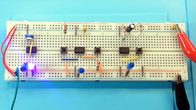
Thank you. An article on basic/entry level stuff is never a bad idea. Now I want to build the setup in the image, if only because it looks cool.
i’m slowly becoming a little competent at using capacitors, resistors, and transistors together to get a complex result…and whenever i do that i always wind up wanting to use a 555 just to get a nice reliable flip-flop that is triggered at a specific voltage. and i feel so stupid that i don’t know any other way to accomplish that, but i do love my 555s!
i also love pic12s, and i don’t care about the cost difference at all…but the pic12s, sometimes i destroy them when programming them, or i program them in such a way that my programmer won’t work on them anymore (it boots up and starts fighting the ICSP pins beforethe cheap RS232-based programmer can establish Vpp or whatever). i’ve wasted whole days trying to figure out why one of the I/O pins on an otherwise-fine PIC12 has simply gone dead. and on top of that, for stupid reasons i’m sure, the pic12 programmer i have only works in windows. but i’ve yet to damage a 555 poking at it on a breadboard. it is just always handy.
555 or micro: both have their place.
But in 5 years, when one fails how do you fix it?
555: Pull the chip, stick in a new one.
micro: find the source code of binary file. Can you still obtain the chip? Do you have a means to program it?
What about in 10 years? Or 20. Or 40?
40 years from now, you’ll use your ion implanting microscope to repair the circuit in situ.
Psh, could’ve done all that with an Arduino… :p
Here is a photo album of the original Signetics 555 data book from 1973.
https://photos.app.goo.gl/2wXNZ1YPSyXk358n7
Warning – it contains cartoons that can melt snowflakes.
555’s and nixie tubes. Urg.
This mentality leads to situations like russians having mach 27 missiles and our government worrying about building a wall. Perhaps if they get the wall built perhaps they will build some trevosheys….
I inherited a bunch of 555-like chips (I think they are “556’s” — two 555-equivalents in one unit) from a lab that was shutting down a few years back. They have been collecting dust ever since. Wondering if anyone has any ideas on how I might use them for a fun project? Something sound related perhaps, like a cheapo analogue synthesizer?
Look for “Atari Punk Console”.
It is possible to attach a LED to reset pin 4 ? This will turn this LED On when reset is received by pin 4 .