Simple CMOS Circuit Allows Power And Data Over Twisted-Pair Wiring

If you need to send data from sensors, there are plenty of options, including a bewildering selection of wireless methods. Trouble is, most of those protocols require a substantial stack of technology to make them work, and things aren’t much easier with wired sensors either. It doesn’t have to be that complicated, though, as this simple two-wire power-and-data interface demonstrates.

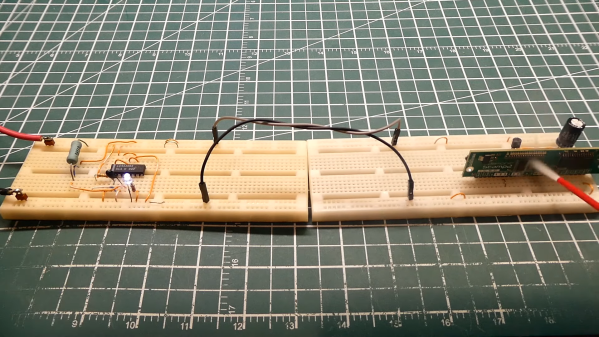
As with all things electronic, there are tradeoffs, which [0033mer] addresses in some detail in the video below. The basic setup for his use case is a PIC-based sensor — temperature, for this demo — that would be mounted in some remote location. The microcontroller needs to be powered, of course, and also needs to send a signal back to a central point to indicate whether the monitored location is within temperature specs. Both needs are accommodated by a single pair of wires and a tiny bit of additional circuitry. On one end of the twisted pair is a power supply and decoder circuit, which sends 9 volts up the line to power the PIC sensor. The decoder is based on a CD4538 dual monostable multivibrator, set up for an “on” time of one second. A trigger input is connected to the power side of the twisted pair going to the sensor, where a transistor connected to one of the PIC’s GPIO pins is set up to short the twisted pair together every half-second. Power to the PIC is maintained by a big electrolytic and a diode, to prevent back-feeding the controller. The steady 0.5-Hz stream of pulses from the sensor keeps resetting the timer on the control side. Once that stream stops, either through code or by an open or short condition on the twisted pair, the controller triggers an output to go high.

It’s a pretty clever system with very simple and flexible circuitry. [0033mer] says he’s used this over twisted-pair wires a couple of hundred feet long, which is pretty impressive. It’s limited to one bit of bandwidth, of course, but that might just be enough for the job. If it’s not, you might want to check out our primer on current-loop sensors, which are better suited for analog sensors but still share some of the fault-detection features.

Continue reading “Simple CMOS Circuit Allows Power And Data Over Twisted-Pair Wiring”

A Cassette Interface For A 6502 Breadboard Computer, Kansas City-Style

It’s been a long time since computer hobbyists stored their programs and data on cassette tapes. But because floppy drives were expensive peripherals and hard drives were still a long way from being the commodity they are today, cassettes enjoyed a long run at the top of the bulk data storage heap.

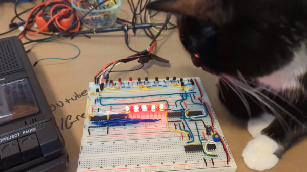
Celebrating that success by exploring the technology of cassette data storage is the idea behind [Greg Strike]’s Kansas City decoder project, which he hopes to use with his [Ben Eater]-style 6502 computer. The video below explains the Kansas City standard in some detail, and includes some interesting historical context we really hadn’t delved into before. There are also some good technical details on the modulation scheme KCS used, which [Greg] used to base his build. After a failed attempt to use an LM567 tone decoder chip, he stumbled upon [matseng]’s KCSViewer project, which decodes KCS-encoded audio signals using nothing but discrete components.

[Greg]’s prototype has a comparator to convert sine waves to square waves, followed by pair of monostable timers, each tuned to either the high or low frequency defined in the KCS specs. A test signal created using Audacity — is there anything it can’t do? — was successfully decoded, providing proof of concept for the project’s first phase. We’re looking forward to the rest of the series, which will turn this into an actual decoder, and presumably add an encoder as well.

Listeners of the Hackaday Podcast may recall we experimented with using KCS to hide some data within an episode a few months back.

Continue reading “A Cassette Interface For A 6502 Breadboard Computer, Kansas City-Style”

Vacuum tube Atari Punk Console

The Atari Punk Console, Now With More Vacuum Tubes

Most of us have beheld the sonic glory of an Atari Punk Console, that lo-fi synth whose classic incarnation is a pair of 555 timers set up to warble and bleep in interesting ways. Very few of us, however, have likely seen an APC built from 555s that are made from vacuum tubes.

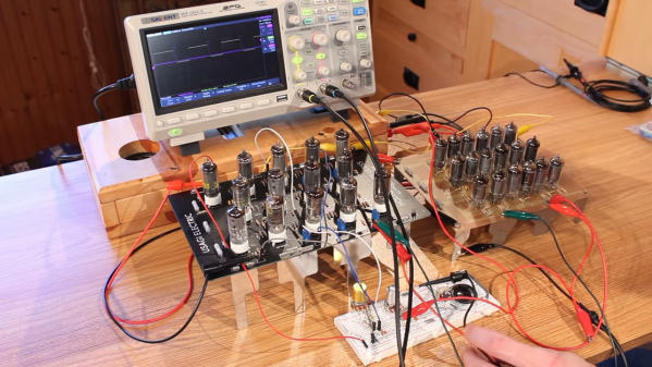
It’s little surprise to regular readers that this one comes to us by way of [David] at Usagi Electric, who hasn’t met a circuit that couldn’t be improved by realizing it in vacuum tubes. His “hollow-state” Atari Punk Console began with the 18-tube version of the 555 that he built just for fun a while back, which proved popular enough that he’s working on a kit version, the prototype of which served as the second timer for the synth. With 32 tubes aglow amid a rats-nest of jumpers, the console managed to make the requisites sounds, but lacked a certain elegance. [David] then vastly simplified the design, reducing the BOM to just four dual-triode tubes. Housed on a CNC milled PCB in a custom wood box, the synth does a respectable job and looks good doing it. The video below shows both versions in action, as well as detailing their construction.

As cool as a vacuum tube synth may be, we realize that not everyone goes for the hot glass approach. No worries — plenty of silicon Atari Punk Consoles to choose from here. There’s one built into a joystick, a circuit sculpture version complete with mini-CRT, or even eight APCs teamed up with MIDI control.

Continue reading “The Atari Punk Console, Now With More Vacuum Tubes”

The Three Faces Of The 555

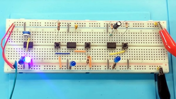
In these days of cheap microcontrollers, it is hard to remember there was a time when timing things took real circuitry. Even today, for some applications it is hard to beat the ubiquitous 555 timer IC. It is cheap, plentiful, and reliable. What’s interesting about the 555 is it isn’t so much a dedicated chip as a bunch of building blocks on a chip. You can wire those building blocks up in different ways to get different effects, and [learnelectronics] has a video showing the three major modes you typically see with the 555: astable, bistable, and monostable.

The 555 is really only a few comparators, a voltage divider, one or two transistors, a flip flop and an inverter. The idea is you use a capacitor to charge and the comparators can set or reset the flip flop in different ways. A reset input or the flip flop can turn on the transistor to discharge the capacitor.

Continue reading “The Three Faces Of The 555”

A 100th Birthday Celebration For The Flip Flop

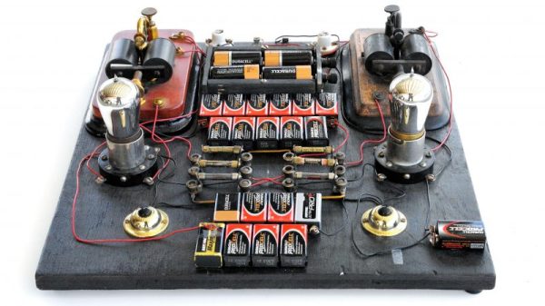
It’s easy to get caught up in the excitement of creation as we’re building our latest widget. By the same token, it’s sometimes difficult to fully appreciate just how old some of the circuits we use are. Even the simplest of projects might make use of elements that were once a mess on some physicist’s or engineer’s lab bench, with components screwed to literal breadboards and power supplied by banks of wet-cell batteries.

One such circuit turns 100 years old in June, which is surprising because it literally is the building block of every computer. It’s the flip-flop, and while its inventors likely couldn’t have imagined what they were starting, their innovation became the basic storage system for the ones and zeros of the digital age.

Continue reading “A 100th Birthday Celebration For The Flip Flop”