Last month we marked the 40th birthday of the CD, and it was as much an obituary as a celebration because those polycarbonate discs are fast becoming a rarity. There is one piece of technology from the CD age that is very much still with us though, and it lives on in the standard for sending serial digital audio between chips. The protocol is called I2S and comes as a hardware peripheral on many microcontrollers. It’s a surprisingly simple interface that’s quite easy to work with and thus quite hackable, so it’s worth a bit of further investigation.
It’s A Simple Enough Interface
Don’t confuse this with the other Philips Semiconductor protocol: I2C. Inter-Integrated Circuit protocol has the initials IIC, and the double letter was shortened to come up with the “eye-squared-see” nomenclature we’ve come to love from I2C. Brought to life in 1982, this predated I2S by four years which explains the somewhat strange abbreviation for “Inter-Integrated Circuit Sound”.
The protocol has stuck around because it’s very handy for dealing with the firehose of serial data associated with high-quality digital audio. It’s so handy that you’ve likely heard of it being used for other purposes than audio, which I’ll get to in a little bit. But first, what does I2S actually do?
A digital audio source will usually create two words of data, one for the left channel and one for the right, once for every sample interval. For example, a CD audio source with a 44.1 kHz sample rate that will deliver two 16-bit words 44,100 times every second. On a single serial line this is a whopping 1,411,200 bits per second (44100 x 16 x 2).
How does that poor serial data line keep up? Well, a single serial data line cannot easily convey the word boundaries for left and right samples. It is also difficult (or impossible) to reliable retrieve a clock from it without jitter. So for transmitting audio we really need some other means of delivering those pieces of information.
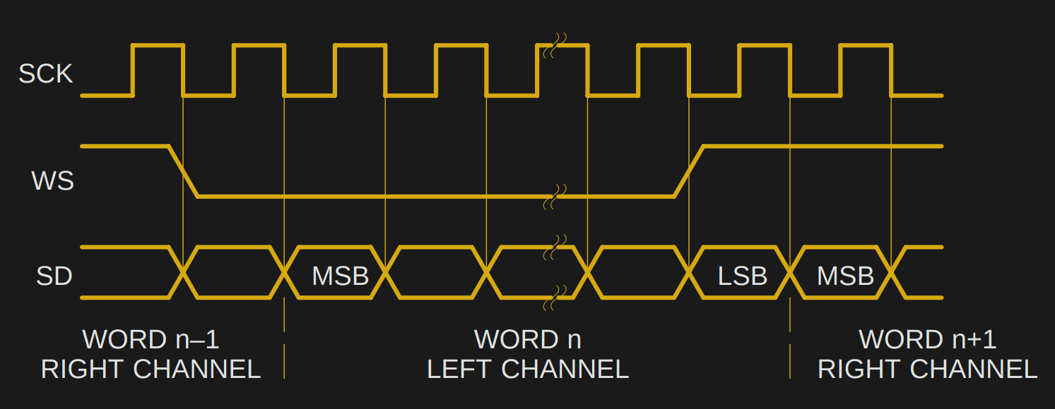
I2S solves both of these problems with extra lines, providing a word select line (also sometimes called L/R clock) to select left or right samples, and a bit clock line to keep everything in sync. That’s all there is to I2S: a data line, a word clock line, and a bit clock line.
The specification was formalised by Philips in a 1986 document that made it through the company’s semiconductor division becoming NXP, but sadly has disappeared from the NXP website. Happily the Wayback Machine has it though, so it is still available. Reading the document it becomes apparent that even in the 1980s this was not a difficult interface to work with, and it even gives basic diagrams for a transmitter and receiver. It’s not impossible to imagine that given some TTL chips and a resistor ladder it should be possible to build an I2S DAC from first principles on your bench, albeit not a very high-performance example.
Where We’re Going, We Don’t Need Audio
![The seemingly impossible: [cnlohr]'s feat of making an ESP8266 do wired Ethernet.](https://hackaday.com/wp-content/uploads/2016/04/10baset-on-esp8266-featured.jpg)
As it happens from the point of view of the work we cover at Hackaday the digital audio origins of I2S are only the start. It is both a loose and a simple specification that is easy to implement, and equally easy to abuse. For example, it does not specify an upper limit for the clock rate. Naturally, its potential as a very fast serial output has led hardware hackers to use it for other purposes. We’ve seen it pressed into service as an AM radio transmitter, an NTSC video output, a VGA output, and even an Ethernet card. How on earth are they doing that!
The answer lies in pulse density modulation, a form of analogue to digital conversion in which the number of logic 1 bits in a given time period depends on the level of the analogue signal. This is the raw output of a delta-sigma ADC, and it has the handy property that given only a PDM data stream the digital to analogue conversion step can be performed with only a simple low-pass filter. If you crank up the bitrate on an I2S interface as far as it will go and then feed it words that form a PDM data stream, you can add a low-pass filter to create an ADC with a maximum bandwidth of half its bit rate.
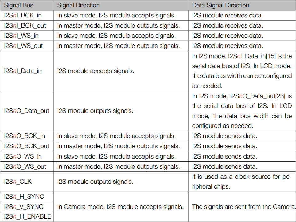
There’s an addendum to the list of example projects above using I2S, and it concerns some of those we haven’t featured. The ESP32 has an I2S module, and through it have come some impressive projects such as this full-colour VGA generator. At risk of skirting controversy though, these projects are not using I2S in the strictest sense. The ESP32 technical reference manual page 303 sheds some light on this, revealing that the I2S peripheral in the Espressif part is multifunctional. As well as handling audio I2S as described above, it also handles interfaces for cameras and LCD displays, it’s as though you were to imagine the camera and LCD connectors on a Raspberry Pi routed to the same piece of silicon. Perhaps this nomenclature has its roots in the ESP8266 having an I2S peripheral on chip (page 71), and the shared peripheral in the later device inheriting the moniker. Either way it might be I2S ESP32-style, but in those two other interfaces it’s not I2S Philips serial PCM audio-style.
Because most I2S interfaces can work with clock rates into the many megahertz, their bandwidth can be surprisingly high. It’s the same as the principle behind any software-defined radio transmitter: at a stroke and with very little extra hardware you have transferred the task of creating arbitrary spectra in the MHz range from hardware to software. Even the most pedestrian of modern microcontrollers have enough computational power for the task, rendering relatively straightforward some applications for I2S that would have been beyond the imaginations of those Philips engineers of the 1980s. Suddenly that one-trick pony to which you could only hook up an audio DAC becomes a lot more useful, and the possibilities are endless.
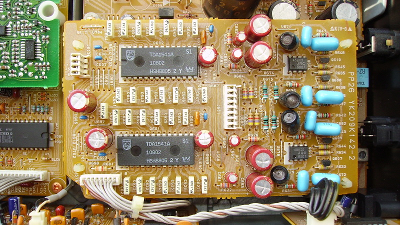
Header image: Philips TDA1541A 4x oversampling I2S DACs in a CD player. Cjp24 [CC BY-SA 3.0].


Don’t forget the “running stepper motors from I2S on ESP8266” trick! https://hackaday.com/2016/09/06/run-a-reprap-on-an-esp8266/
I got to learn this protocol quite quickly by fixing CD players with the venerable TD1541A DAC pictured. I don’t think a better 16 bit chip was ever produced. Sadly all the NOS chips that come up now are fakes or the relaxed spec R variant, unless anyone knows any different?
The TDA1547 was (alledgedly) an even better D/A converter than the venerable TDA1541. It needs an SAA7350 for its timing signals. Both are exceedingly rare.
I thought it was pronounced “aye-squared-sea”.
That’s I2C. It’s a whole different kettle of fishes.
I2S is fast, 3-wire, and intended for audio.
I2C is slow(er), 2-wire, and good for all sorts of random peripherals, chained together as a bus.
Can this be only used for Stereo signals (aka 2 channels) ? What about other sound architectures such as 5.1 or 7.1 ? Are there implementations where multiple I2S (WS and SD), sharing the same SCK, are used so that the total number of channels can go up to 6 or 8 ?
Yes. 5.1 and 7.1 channel Linear PCM is transported using additional data pairs (bit clock and word clock is shared). Don’t confuse it with HBR (High Bit Rate) Audio used to send compressed audio over the same pairs in specific situations such as the interface to HDMI transceivers. HBR can be turned on and off dynamically mid-stream as the content changes.
There is also a Time Division Multiplexed (TDM) variation where the word clock becomes a frame sync strobe. It goes high for one bit clock period at the start of each frame. It is up to the sender and receivers to pre-assume the frame length, bits per channel, senders for each channel etc. In TDM systems there is one clocking master and each node generally floats the data line (or lines) until their assigned channel number (or numbers) to start clocking out data. It can be bi-directional in this regard. 8 and 16 channel TDM systems are common.
There is also a variation of I2S usually simply referred to as ‘left justified’ where the word clock is aligned to the data instead of being shifted one bit period ahead in I2S.
Just like with IEC-60958 (the SPDIF standard), the protocol can easily be expanded so that WS=LOW means the first channel (usually the Left channel) followed by any number of samples for other channels where WS=HIGH.
Better to go with the self-clocking ADAT standard.
I used I2S to interface to audio converters for this IN-9 Nixie audo level meter project:
https://twitter.com/bikerglen/status/1013252383646744576
RTL for the (somewhat crude) I2S interface is on github:
https://github.com/bikerglen/fpga-in9-audio-meter
Another nice feature of I2S is that the most significant bit is send first, and the number of bits is not dictated. It can be used for 8-bit audio, 32-bit audio, or whatever number of bits you have available. This is even “officially” supported, even when there is a mismatch between sender and receiver. If you send a 12 bit resolution signal to a 16-bit dac it should “just work”. (with the last 4 bits zet to zero).
Talking about LED’s. I2S is also being (ab-) used for talking to WS2812
https://duckduckgo.com/?q=ws2812+I2S&ia=software
A good implementation o I2S hardware and software can be found on PJRC.com. The associated Teensy library and PJRC’s audio adapter board made my first pass at a hearing aid a feasible project.
And before Ms. List and others ask why solve an already solved problem, they need to know that a pair of marginally functional hearing aids in the U.S. cost $3000 to 10000 USD. So doing the engineering for the design iterations (the third version is being used) was definitely worth my time.
I certainly would never ask such a question. If you have anything you’d like to share from your hearing aid project, please do submit it to the tips line.
Id like to know more of this – hearing aids in Austrlalia are equally rediculously priced and Nursing homes like loosing them….
The chips for Digital Compact Cassette (DCC) recorders and players use the I2S protocol for transporting the PASC (MPEG 1 layer 1) bits between chips. The bit clock there is twice the usual bit rate for PASC: 768 kilobits per second, but the data only uses half the bandwidth: two bytes per data word, so the effective data rate is 384kbps.
I speculate that, by using double the bit rate and half the bandwidth they could simplify the hardware inside the chips: it was probably easier for the internal hardware to read the serial-to-parallel converter or load the parallel-to-serial converter during the time that no data was shifted in or out, without having to worry about glitches or double buffering.
Or maybe they did it that way to reserve bandwidth for a future expansion of the protocol.
Either way: Pretty nifty for 1992!
I drive ws2812 led matrix with i2s: https://github.com/juju2013/nrf52-forth-lib/blob/master/lib/ws2812.fs
What? How is I2C shorter than IIC? I’ll just ignore the fact that there is no superscript 2 button and that one must do something funny and multi-click/press just to make it and those are still the same number of characters!
This is pure speculation, but i would imagine that saying eye-eye-sea would lead to confusion based on the tendency for people to repeat the beginning of a word either as a stutter or just a kind of brain reset in the middle of the word. Whatever the reason you dont see many three letter repeats for oft used phrases. And if im wrong someone correct me.
So then it goes to either double-eye-sea or Eye-square(d)-sea which has the benefit of one less syllable and is less clunky i guess. That said i also have seen it written very often as I2C and occasionally said as eye-two-sea. Which is the same syllables and doesnt require a superscript.
Ok so for three letter repeats ive got pee-pee and poo-poo so far. Not the best company to be in.
Every engineer knows I^2 is -1, so maybe it should just be simplified to
“-C”?
it was an 80’s vogue
Have never formally GPL’d or open-sourced anything, and based on past experience, is not worth the risk. But for those interested in ideas for this subject, the Tympan project does a good job of documentation. My first HA design was done prior to this, and uses a different approach, but the Tympan project is a more general solution and is more apt to provide a better starting reference than mine.
openaudio.blogspot.com
tympan.org
I-too-see
On 18-April-2019 Jenny List said: “The [I2S] specification was formalised by Philips in a 1986 document that made it through the company’s semiconductor division becoming NXP, but sadly has disappeared from the NXP website. Happily the Wayback Machine has it though, so it is still available.[1]”
1. Original I2S Specification c.1986 – NXP
https://web.archive.org/web/20080706121949/http://www.nxp.com/acrobat_download/various/I2SBUS.pdf
The current official I2S specification has been available on the NXP web site since 2022.[2] The two documents are essentially the same:
2. I2S Specification – NXP Semiconductors – UM11732
©NXP B.V. 2022. All rights reserved.
Date of release: 17 February 2022
Document identifier: UM11732
https://www.nxp.com/docs/en/user-manual/UM11732.pdf