Frequency counters are useful tools for anyone that finds themselves regularly working with time-variant signals. There are a huge range available, from cheap eBay specials to expensive lab-grade hardware. [itakeyourphoto] had a counter on the lower end of the cost spectrum, and decided to make some improvements with the help of GPS (Youtube link, embedded below).
The fundamental weakness of a cheap frequency counter is usually the internal reference against which all other signals are measured. The more accurate this is, the more accurate the counter will be. [itakeyourphoto] determined that a great way to generate a reasonably good reference frequency was by using a uBlox GPS module. Once locked on to satellites, it can use a numerically controlled oscillator to output any frequency up to 15MHz with good accuracy.
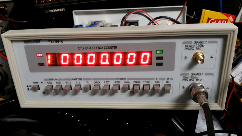
The cheap frequency counter in question used a 13 MHz internal reference, so the uBlox module was programmed to match this. [itakeyourphoto] reports that it compares favorably to his higher-end GPS-disciplined oscillators, displaying very little drift or other aberrations.
We see plenty of clocks using GPS for its accurate time, but we’ve seen projects that attempt to go even further than that, too. Video after the break.
[Thanks to jafinch78 for the tip!]


Looks like a pretty easy mod, I was half expecting you to have to slap in an Arduino or such as well.
There will be a lot of jitter on that 13MHz output, because the uBlox module has a 48MHz internal clock, and the transitions will be synchronous with that. Since 48/13 is not an integer, the 13MHz output will be “irregular”.
Even if you choose a different frequency (e.g. 16, 8, 4, 2, 1MHz), there will still be occasional 21ns steps in the output.
Key search phrase for understanding the topic: “Allen Deviation”.
Such points matter to timenuts, i.e. someone with an 8 digit meter: :)
For a frequency counting application this may not be a disaster, if the gate time is long enough…
That is where you would use a jitter attenuator like the SI5342A used in this project ( https://www.sv1afn.com/gpsdo.html ). The schematic is in a pdf linked near the bottom of the page (search for “Schematic Diagram”).
The heart it is a jitter attenuator and two clock sources one with good short term stability (50MHz +/- 1ppm TCXO) and one with good long term stability (NEO7M) but really dire jitter, the jitter attenuator calculates the parameters of the each during initial calibration period and uses both to reduce the drift and jitter of it’s own internal DSPLL ( ref: https://www.silabs.com/products/timing/oscillators/dspll ). Of course you also need a MCU of some type (for serial and/or SPI to configure the GPS module and send/receive configuration and calibration data to/from the jitter attenuator), eeprom/flash, and lots of LDO’s!.
I made something like this for 10 MHz. There’s a lot of spurs and no filter can remove that. Some measurements are here https://la3za.blogspot.com/2019/05/more-spurs-than-i-had-hoped-for.html
Would it be better if filtered through the original 13 MHz crystal? Figure crystals can act as sort of a high-Q filter, and while it surely wouldn’t be up to the standards of time-nuttery, it would probably clean up some of the jitter.
Even setting aside the jitter caused by the quantization error, GPS itself is going to have relatively poor short term stability. GPS ADEV is more or less a straight line decade-for-decade plot with 10^-8 at around 10^0. Why that matters is that to calibrate something you should generally be using a standard that’s more stable by an order of magnitude or else you’ll need to degrade your observations.
This all may sound like just time nuttery, but I needed to get a proper GPS disciplined OCXO to be able to get decent calibration for 10 ppm crystals in cheap quartz clock movements.
Thanks for the reply, Nick!
You can see the jitter here of a ublox n8m. It’s why i didn’t do a pll gpsdo.
https://www.youtube.com/watch?v=BGcNZM_X1IY
Look here. This is an exemple of ublox jitter like Tom said. https://www.youtube.com/watch?v=BGcNZM_X1IY
When i did my gpsdo, i didn’t do a pll type because of that. pll was sticking on a moving waveform. So i choose another method to have a 1ppb on 10mhz.
https://www.instructables.com/id/GPSDO-YT-10-Mhz-Lcd-2×16-With-LED/
Are you aware if a gps module have no jitter ?